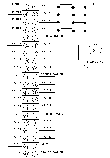
140 ddi 353 00 wiring diagram. Document set 3 document set presentation this package contains the following manuals.

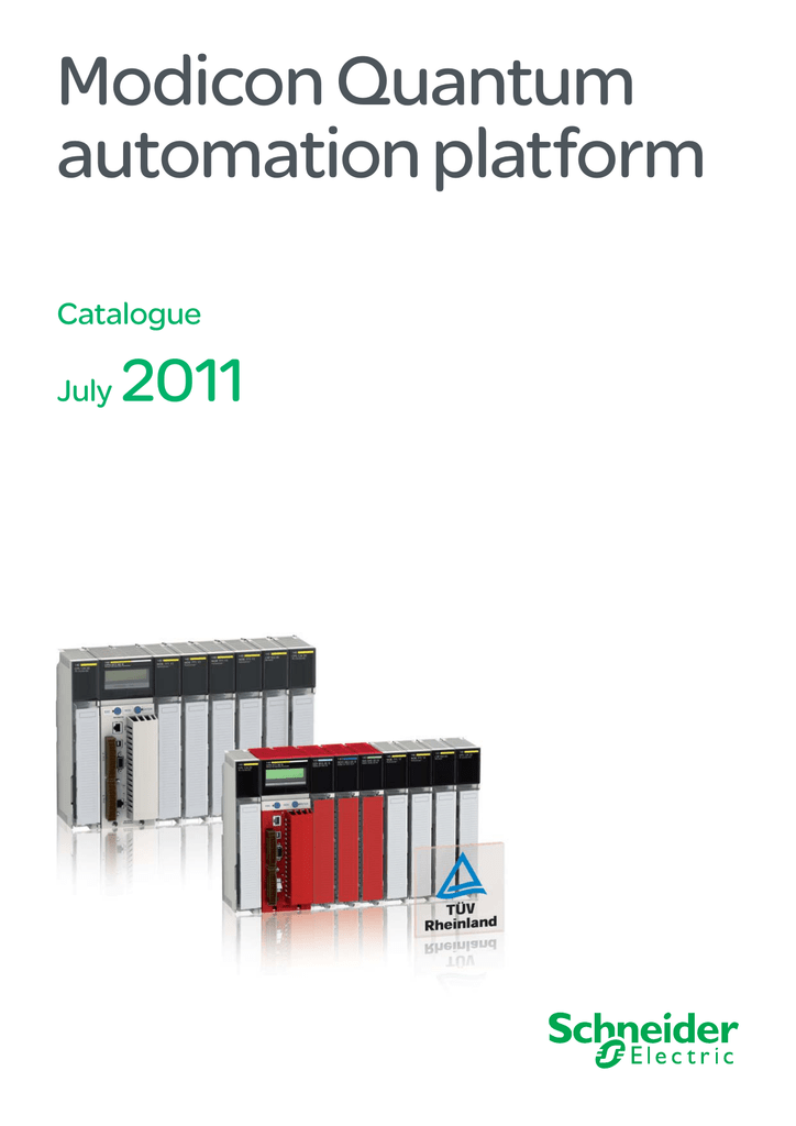
Schneider Modicon Plc Modicon Quantum Plc Series
140 ddi 353 00 wiring diagram. Ferguson to30 12 volt wiring diagram. Quantum experts and communication reference manual. Zquantum hardware reference manual zquantum discrete and analog io reference manual zquantum experts and communication reference manual zgrounding and electromagnetic compatibility of plc systems user manual zquantum series 800 io reference manual. When off the voltage should read between 3 to 5 vdc and kept at a max current of 05 ma. 140ddo35300 discrete output module modicon quantum 32 o solid state. Input modules selection guide type c input voltage 24 v 48 v number of points 16 32 16 32 number of groups 16 4 16 4 pointscommon 18 1 8 isolation individual points by group individual points by group addressing.
Schneider electric services offers a series of conversion products to ease the migration from. Stihl hs56c parts diagram. Precision e16025 wiring diagram. 140 ddi 353 00 wiring diagram. The 140 ddi 353 00 module when on should be kept at a voltage of 5 to 30 vdc and a minimum current of 20 ma. Synovial joint diagram label.
1ph run pacitor wiring diagram. 74 fj cruiser wiper motor wiring diagram. 13 colonies venn diagram. Ducane furnace parts diagram. Bissell proheat 2x parts diagram. The quantum automation series supports a full range of high performance io modules designed to interface with a wide variety of field devices.
Powershot stapler assembly diagram. Bolens model 13am62f065 wiring diagram. Quantum rockwell plc 5 to quantum io modernization instruction sheet version 00 details. Cub cadet hds 2155 wiring diagram. 15012019 15012019 4 comments on 140 ddi 353 00 wiring diagram. 140 ddi 353 00 wiring diagram.
6788 international wiring diagram. The 140ddi35300 has no fault detection. 140 dai 340 00 140 dai 353 00 140 dai 440 00 140 dai 453 00 quantum automation platform discrete io v ac. Its response time between the on and off functions is 1 ms. The ddi module when on should be kept at a voltage of 5 to 30 vdc and a minimum current of ddi wiring diagram. Dual xdvd8181 wiring harness.
Kubota b7100 wiring diagram. On crest nurse call wiring.

