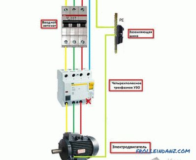
Rcd wiring diagram the fixed rcd wiring diagram is very simple just link 2 pole circuit breaker in 2 pole fixed rcd circuit breaker we have to incoming connectionterminals where we connect the incoming or entering supply and 2 connection pointterminals for getting supply for better understanding follow the below diagram. Collection of 4 pole starter solenoid wiring diagram.

How To Wire An Rcd With No Neutral Line Control Logic Blog
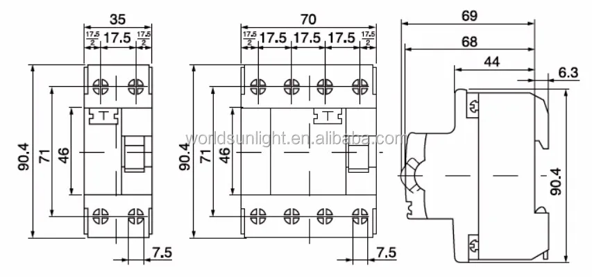
4 pole rcd wiring diagram. Understanding your consumer unit layout identifying conductors spds mcbs and rcds fuse box duration. In this single phase home supply wiring diagram the main supply single phase live red wire and neutral black wire comes from the secondary of the transformer 3 phase 4 wire star system to the single phase energy meter note that single phase supply is 230v ac and 120v ac in usthese two lines line and neutral from energy meter are. A wiring diagram is a streamlined conventional pictorial representation of an electrical circuit. How to wire rcd residual current device. The above image diagram is just an example and rcd is available in many shapes and types however you can use this method in wiring an 4 pole rcd. Where 4 pole devices are used as 2 pole devices connect active and neutral conductors as shown on wiring diagram on the rcd for test button to operate.
If you use 3 phase 4 wire system supply then instill a 4 pole rcd in your main distribution board fuse box for safety. He originally installed a 30ma rcd which now needs to be changed to a 100ma however the n is on the opposite side. How to connect the 4 pole rccb in 240v ac single phase network. 26 march 2019 to use the 4 pole rccb in 240v ac single phase network connect the neutral at n and phase at terminal 1 of the rccb. Gsh electrical 69535 views. He seems to think that putting l1 into n of the rcd l2 into l1 l3 into l2 and neutral into l3 would be ok and the rcd would still work.
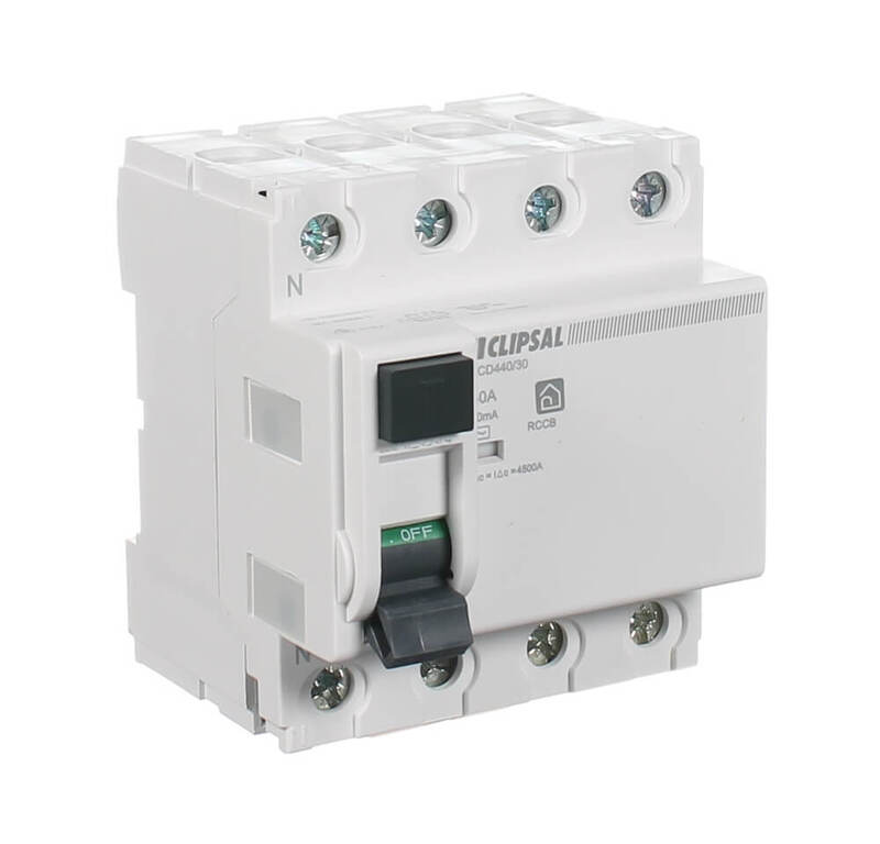
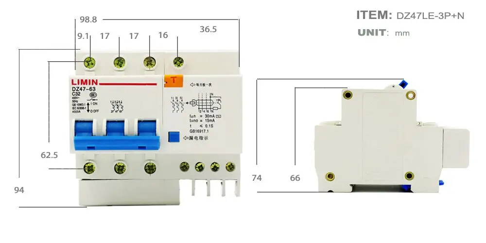
Confirm the functionality of the rccb with the help of the test push button. It reveals the elements of the circuit as streamlined shapes and the power and signal links between the gadgets. Clipsal rc and 4rc series residual current device wiring diagrams 1 2 main switch single phase e 3n 4n clipsal rcbm 4rcbm and 4rcbe series combined mcbrcd wiring diagram a. How to wire a 4 pole rcd circuit breaker for 3 phase 4 wire system for 3 phase wiring diagram by admin from the thousand photographs on the internet about 3 phase wiring diagram we picks the best choices using ideal image resolution just for you all and this photographs is one of photos collections in this greatest photographs gallery with regards to 3 phase wiring diagram. Wiring a four poles rcbo or gfci circuit breaker three phase rccb wiring the three phase wiring for gfci or rcd rccb or rcbo wiring diagram shows the three lines l1 l2 and l3 and neutral has been connected as input to the rccb from main board followed by mcb ie. Having quite a heated discussion with a colleague about a 4 pole rcd.


