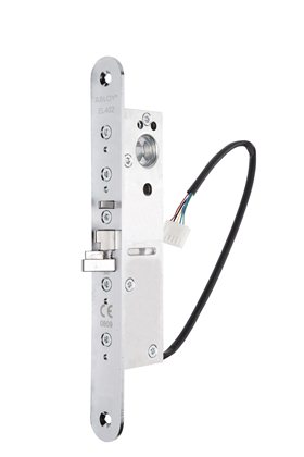
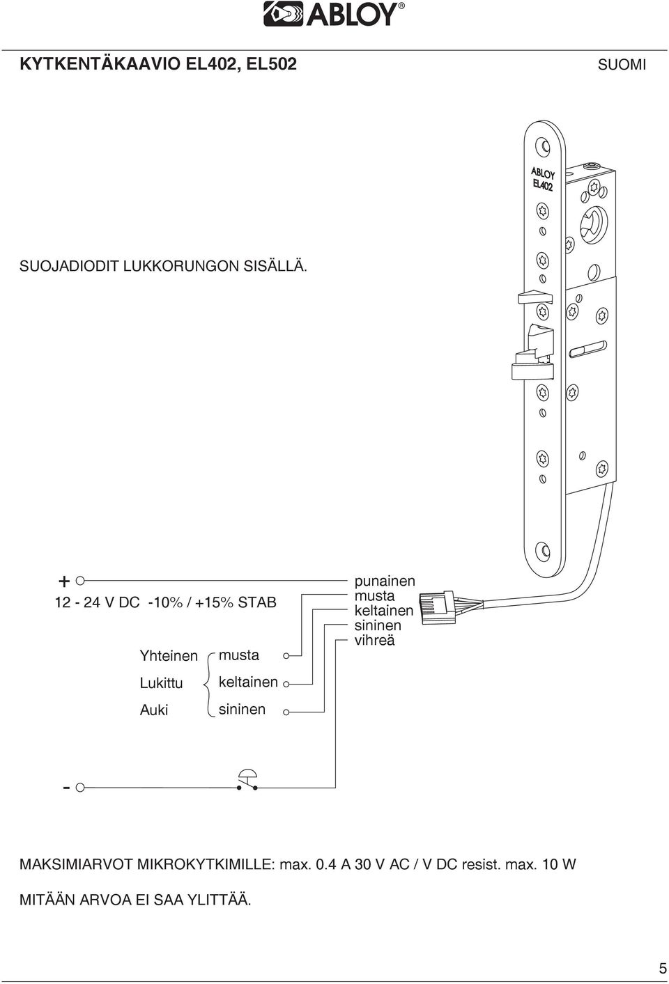
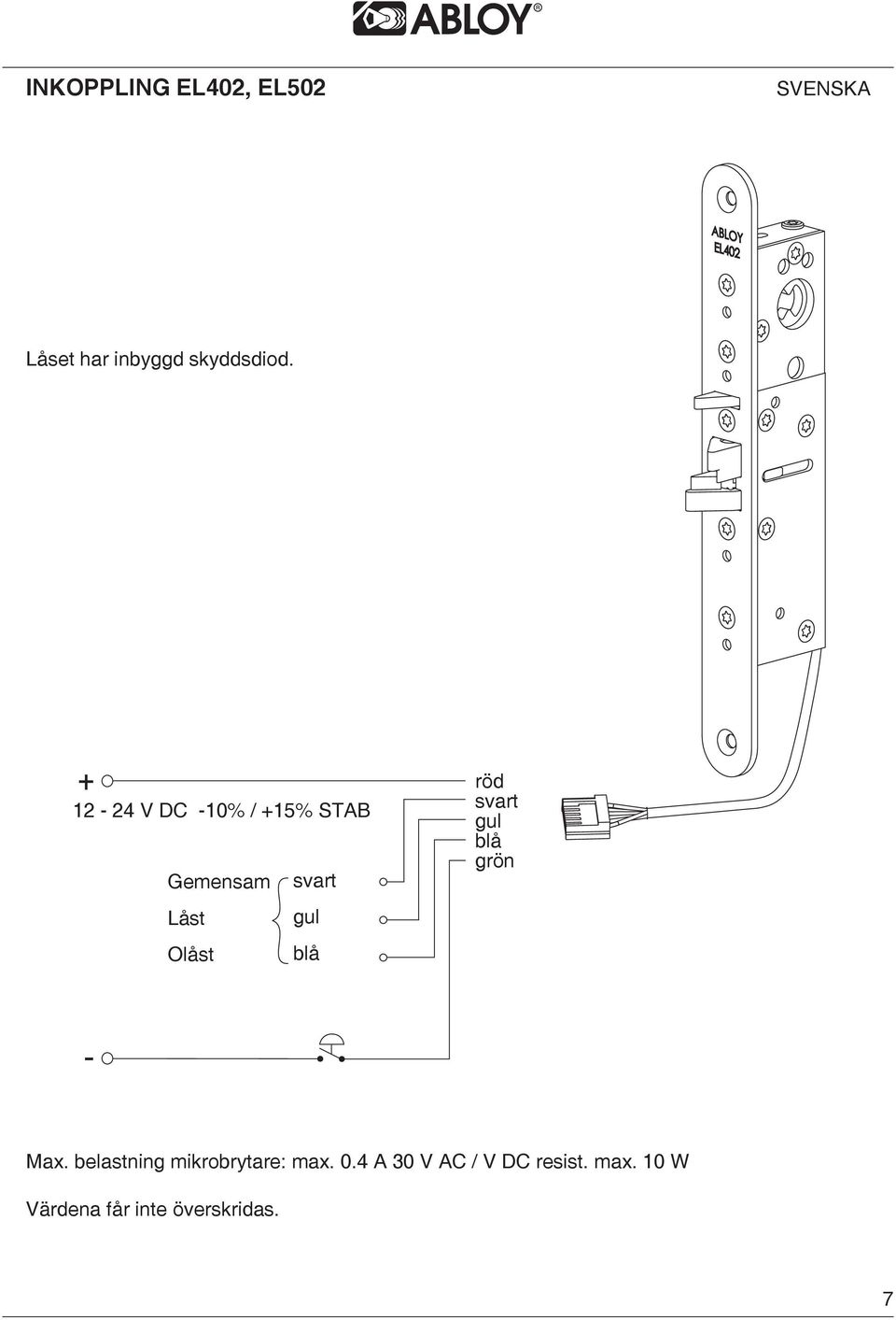
10 w no values to be exceeded. Abloy el402 can be controlled by a variety of electrical impulse generating equipment such as card reader keypad or timer.

Super 8 Manual Digital Lock By Gb Locking Systems Ltd
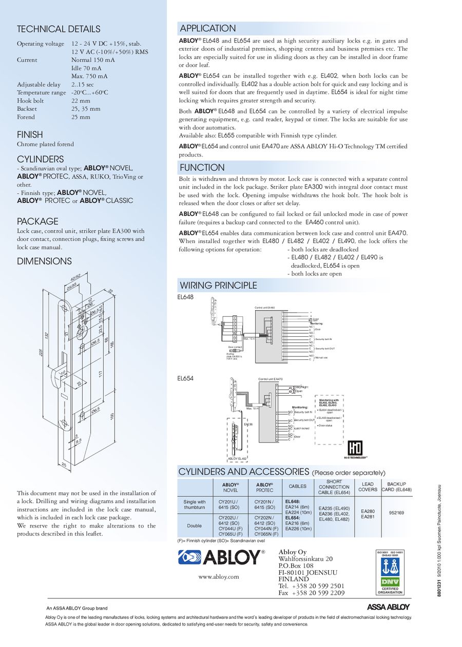
Abloy el402 wiring diagram. The locks can be connected to automatic swing door. Drilling and wiring diagrams ans installation instructions are included in the lock case manual. 04 a 30 v ac v dc resist. Wiring diagram el402 el502 english lock case includes protection diodes. Maximum values for micro switches. 10 w no values to be exceeded.
Wiring diagram el402 el502 english lock case includes protection diodes. Box 108 fi 80101 joensuu finland tel. Wiring diagram el402 el502 english lock case includes protection diodes. El480 el482 el402 el490 is deadlocked el654 is open both locks are open wiring principle abloy oy wahlforssinkatu 20 po. Red black yellow blue green black yellow blue common locked open 1 4 v dc 10 15 stab 10. Black 12 24 v dc 10 15 stab yellow blue green common black locked yellow open blue maximum values for micro switches.
04 a 30 v ac v dc resist. 04 a 0 v ac v dc resist. The latch bold must be no less than 145mm with complete double action trigger. Single door controlled egress wiring diagram 01 single door digital entry wiring diagram 10 single door dk 26 with door prop alarm wiring diagram 15 single door dk1 11 xms dt 7 wiring diagram 20 single door dk 26 remote release wiring diagram 14 single door dk 26 unl 24 and dt 7 wiring diagram 18 single door dk 26 using the hard code to toggle lock off and on wiring diagram. Abloy el402 solenoid lock specification statement the mortice lock must consist of high grade pure zinc alloy the lock needs to have an adjustable backset 25283033 and 35mm. 12 24 v dc 10 15 stab common locked open black yellow blue red black yellow blue green maximum values for micro switches.
