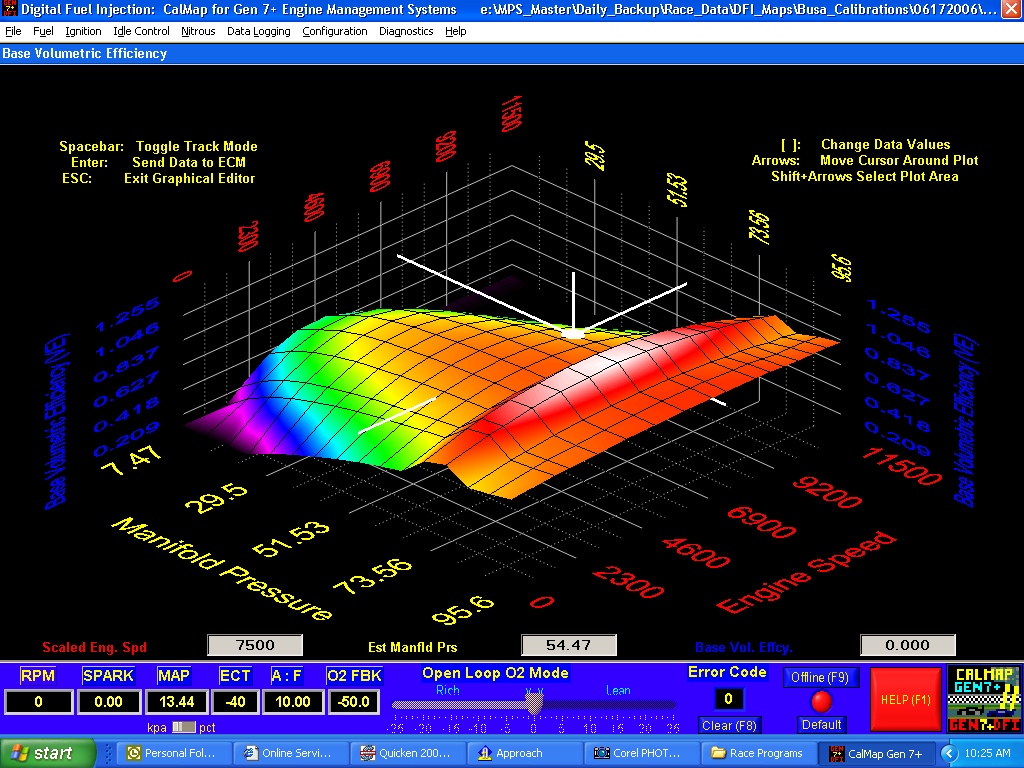
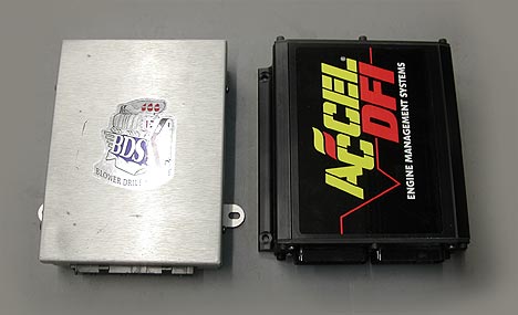
I havent personally run any dfi stuff but thats the direction im leaning for my ecu soon and several of the speed shops around here have been installing the stuff for years with good results. Online access to help schematics and wiring diagrams an additional 8 status indicators are available through the gen 7 logging feature a dfi exclusiveaccel dfi gen 7 wiring diagram thank you for visiting our site this is images about accel dfi gen 7 wiring diagram posted by maria rodriquez in diagram category on nov 13 you can also.

Old School Dfi Gen 6 Pinout Needed Third Generation F Body
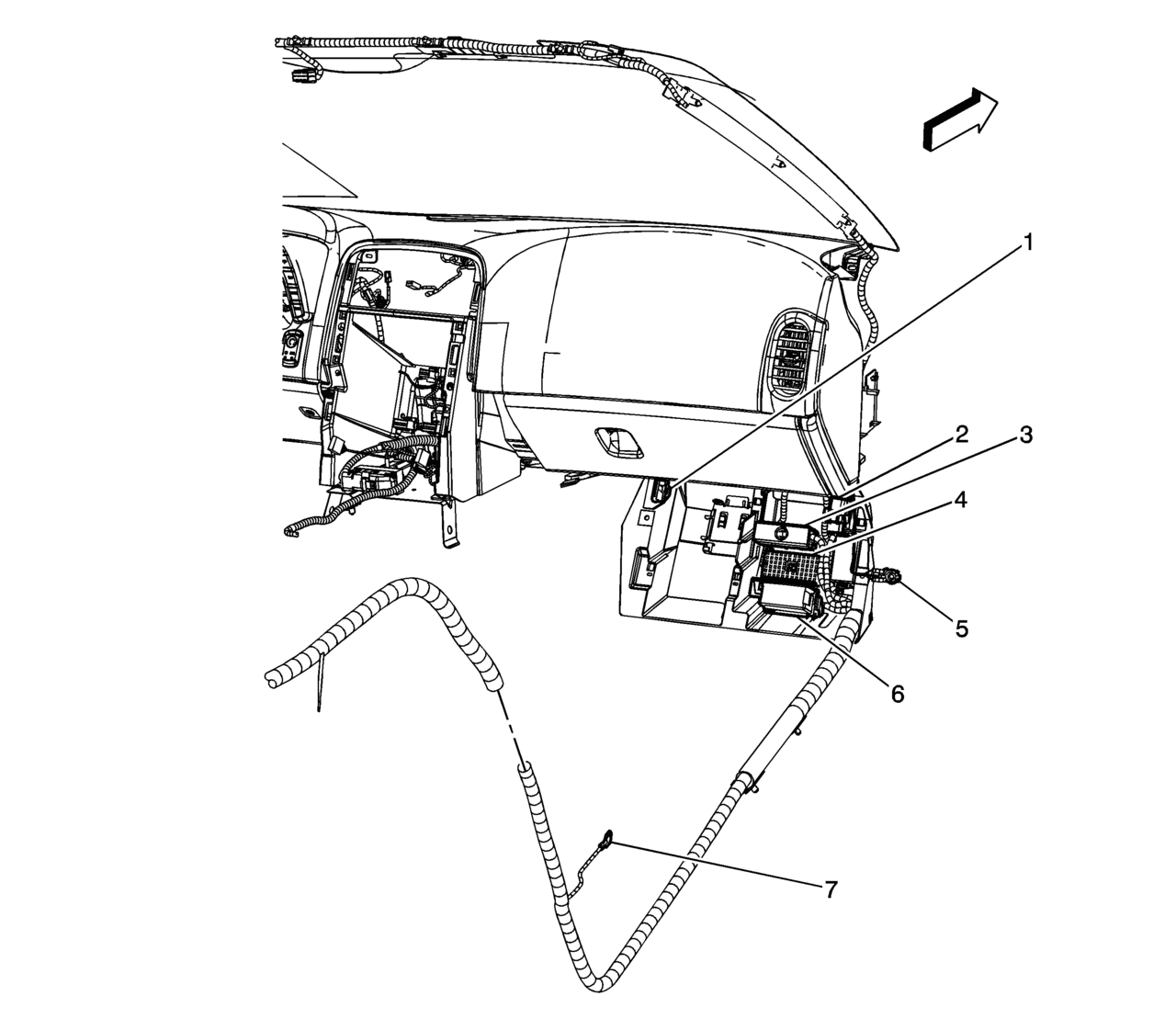
Accel dfi gen 6 wiring diagram. An overview diagram of the main wiring harness is shown at the end of this section. The harness can be routed and connected as follows. 0 bidsfuel injection specialties is a supplier of oem and specialty fuel systems providing parts. Online access to helpschematicsand wiring diagrams. 6 acceldfi two legs through the drivers side firewall hole that you cut in step two followed by the shorter leg though the. Acceldfi engine management systems dfi generation 70 installation and operation manual.
46 4v accelholley dfi gen 7 wiring help. The multi color led sweep display around the perimeter of the gauge face is specially calibrated to provide instant feedback to the driver by changing colors as the airfuel ratio range varies. Then route the longer of the two legs through the drivers side. Acceldfi generation 7 programmable engine management systems most capable in additioneach and every dfi generation 7 engine control module is capable of controlling a wide variety of both standard and optional accessory items. The accel dfi airfuel ratio gauge is designed specifically to operate with this controller. We also build and modify wiring harnesses to accept accel gen 6 gm 50 57 tpi dfi fuel injection system harness ecm.
Will talk about basics of ecuaccel ecm pro software key communication cableaccel dfi. Yes the gen 7 and gen 8 systems and components are even more sophisticated but your gen 6 should still do the job i would think. Please reference this when making the connections between the ecm and the corresponding. Pic is of the swap 95 teksid block and stock refreshed internals 99 continental c heads and cam. Any help would be appreciated. Each module also includes.
Jump to latest follow 1 4 of 4 posts. Acceldfi acceldfi an overview schematic of the main wiring harness mwh is shown in figure b page 23. Thankfully most everything is labeled but i am in need of the ignition wiring diagram hopefully running a stock ford edis 8. Begin by connecting the 32 pin and 24 pin ecm connectors to the acceldfi ecm making sure that the tabs snap into place.


