12do not attempt to operate unit until service valves have been opened. Hvac control wiring diagram examples hvac wiring diagrams wiring.

To 9453 Electrical Wiring Jobs
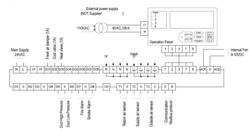
Ahu panel wiring diagram. Contact the poteau panel unit at 918 647 2195. Hvac control panel wiring diagram collections of best how to read wire diagrams electrical outlet symbol 2018. 77 80 intrument panel page 1 77 80 intrument panel page 2 81 87 81 87 cab interior page 1 81 87 cab interior page 2 81 87 chassis and rear lighting 81 87 front lighting 81 87 i6 engine compartment 81 87 v8 engine compartment 81 87 instrument panel page 1 81 87 instrument panel page 2 81 87 computer control wiring power windows wiring. 8 air handling units fans and pumps 81 the field electrical wiring for other major components in central hvac system field power wiring for other major components in central hvac system like pumps fans and ahus are also a single point connection as in the case of chillers but we must use some type of motor starters orand variable. It shows the components of the circuit as simplified shapes and the facility and signal friends in the company of the devices. Thermostat wiring diagrams for heat pumps heat pump thermostat wire diagrams.
Always refer to your thermostat or equipment. Ahu panel wiring diagram wiring diagram is a simplified enjoyable pictorial representation of an electrical circuit. Johnson controls poteau panel unit facility can lay out mount and wire these enclosures to your requirements. Assortment of rheem air handler wiring schematic. 18 gauge standard single stage heat thermostat standard ac condenser ac contactor 4 this diagram is to be used as reference for the low voltage control wiring of your heating and ac system. Ahu103 low voltage wiring conduit line voltage conduit from 120 vac supply power supply transformer relay module fm kit zone.
Wiring diagram maker free simple diesel generator control panel. A wiring diagram is a streamlined standard photographic depiction of an electrical circuit. 11check all electrical connections inside control box for tightness. It reveals the parts of the circuit as simplified shapes and the power and signal links between the devices. Compressor must be off 3 minutes to allow pressures to equalize. 13do not rapid cycle compressor.
3ø wiring diagrams 1ø wiring diagrams diagram er9 m 3 1 5 9 3 7 11 low speed high speed u1 v1 w1 w2 u2 v2 tk tk thermal overloads two speed stardelta motor switch m 3 0 10v 20v 415v ac 4 20ma outp uts diagram ic2 m 1 240v ac 0 10v outp ut diagram ic3 m 1 0 10v 4 20ma 240v ac outp uts these diagrams are current at the time of publication. Wiring diagram for residential ac new wiring diagrams for hvac new. 10if any of the original wire as supplied must be replaced use the same or equivalent wire. Standard ac with standard air handler and single stage backup heat control wiring standard air handler wire size. Heat pumps are different than air conditioners because a heat pump uses the process of refrigeration to heat and coolwhile an air conditioner uses the process of refrigeration to only cool the central air conditioner will usually be paired with a gas furnace an electric furnace or some other method of heating. Ahu controllerair handling unit controller ahu 5 note.
