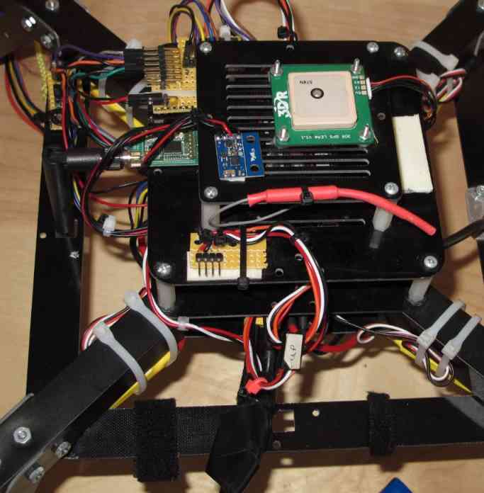
Apm 28 devo 7e tx devo rx701 receiver mavlink mini osd ublox 6m gps module power module 3dr radio telemetry 915 mhz. All is mounted on the skywalker.
Archived Apm2 X Wiring Quickstart Copter Documentation
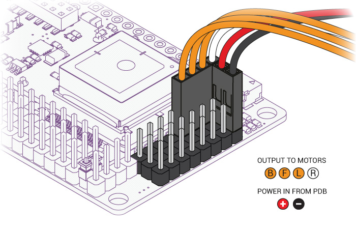
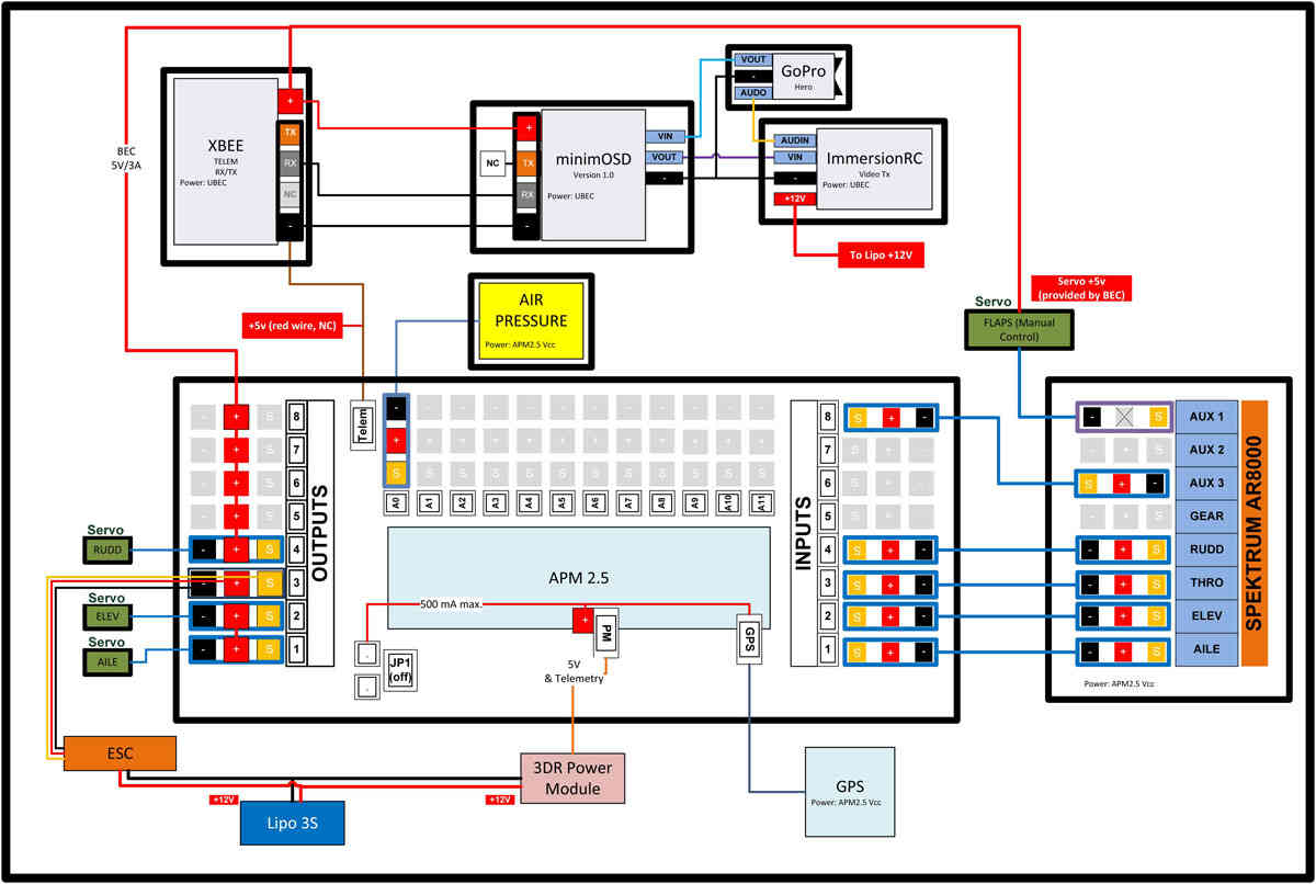
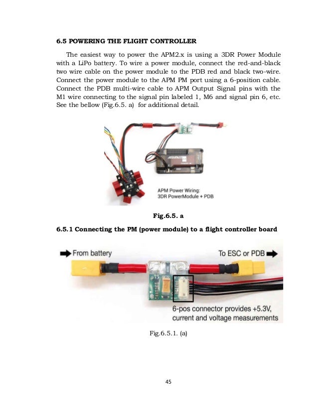
Apm 2 8 wiring diagram. F550 quadcopter hexacopter frame xxda2212 13t 1000kv motor xxd 30a esc. The diagram below is an overview of how an apm2 can be connected to a to apm output signal pins with the m1 wire connecting to the. Hello guys in this video you will quick learn about apm 28 setup installation esc wiring part 1 100 successful latest 2019 ii full video tutorial. Apm 26 receiver wiring apm 26 schematic pdf apm 28 manual pdf arducopter 28. Auto pilot rc drone ardupilot apm ardupilot apm connect the ardupilot apm to the computer via usb cable. Connect the pdb multi wire cable to apm output signal pins with the m1 wire connecting to the signal pin labeled 1 m6 and signal pin 6 etc.
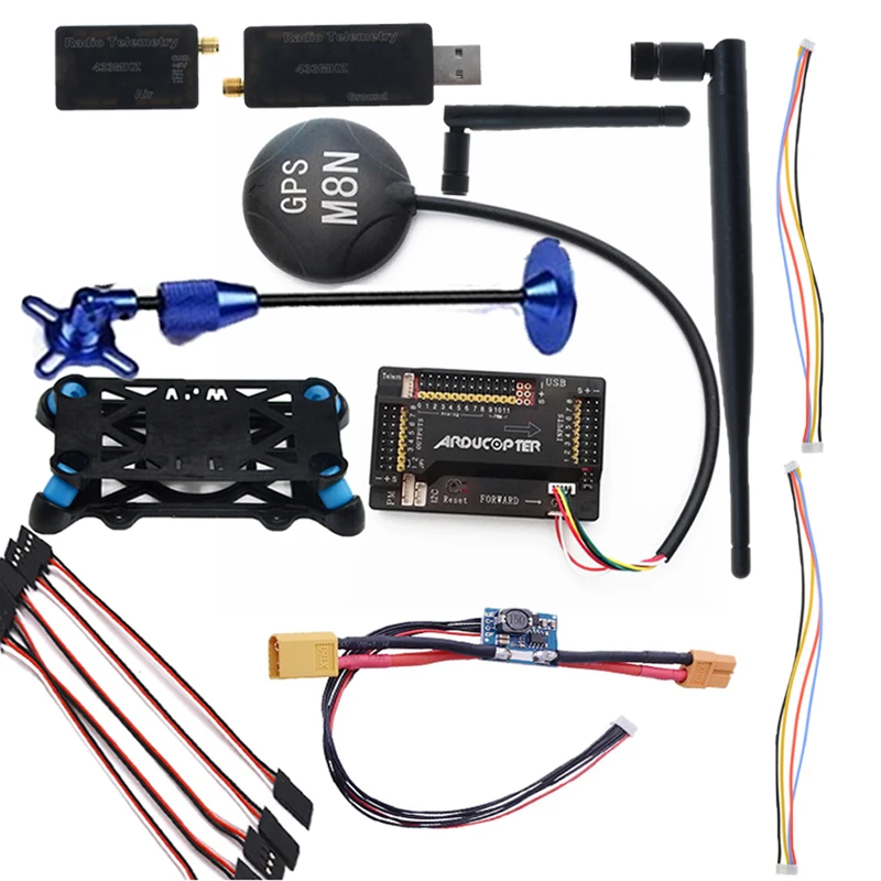
One 4 position cable and one 5 position to 6 position cable. 27112018 27112018 5 comments on apm 28 wiring diagram. Apm 28 wiring diagram. To connect the gps module to apm 26 connect the gps to the apm gps port using the 5 position to 6 position cable. Reviewing wiring schematic and hook up wires for the ardupilot mega 26 to the ezuhf receiver. Heartly thanks for watching this video.
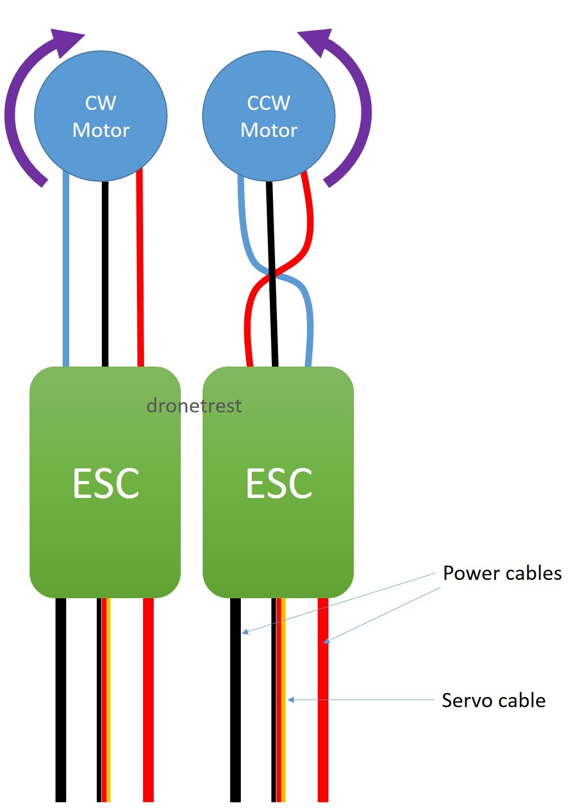
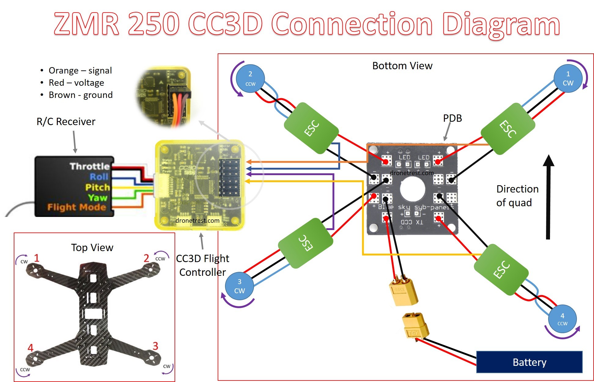
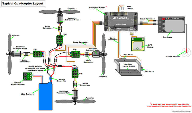
I have connected the receiver to the apm and the tx and tested configured using mission planner and connected the escs. Apm wiring diagram the diagram below is an overview of how an apm2 can be connected to a receiver esc gps and even a camera gimbal. A wiring diagram usually gives opinion about the relative aim and conformity of devices and terminals on the devices to incite in building or servicing the device. Arducopter 28 wiring building your first arducopter. Whether its for kids or youngsters drones have if any motor is moving opposite then just reverse the two side wires from esc to. Apm 26 wiring wiring diagrams 19 apm 26 vs 28 wiring diagram ardupilot mega 2.
Apm wiring diagram the diagram below is an overview of how an apm2 can be connected to a receiver esc gps and even a camera gimbal. Connect the gps to the apm i2c port using the 4 position cable. Apm wiring diagram wiring diagram is a simplified okay pictorial representation of an electrical circuitit shows the components of the circuit as simplified shapes and the capacity and signal associates amongst the devices. Connect the pdb multi wire cable to apm output signal pins with the m1 wire connecting to the signal pin labeled 1 m6 and signal pin 6. The diagrams on the page below is for v1 and v2 which have molex clickmate. We make extension cables for the 3dr telemetry radio and minumosd.
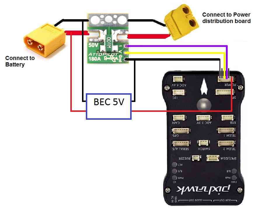
I build my first quadcopter which is the f with apm but my problem is. Connect the power module to the apm pm port using a 6 position cable. 3dr gps ublox with onboard compass includes two connector cables.

