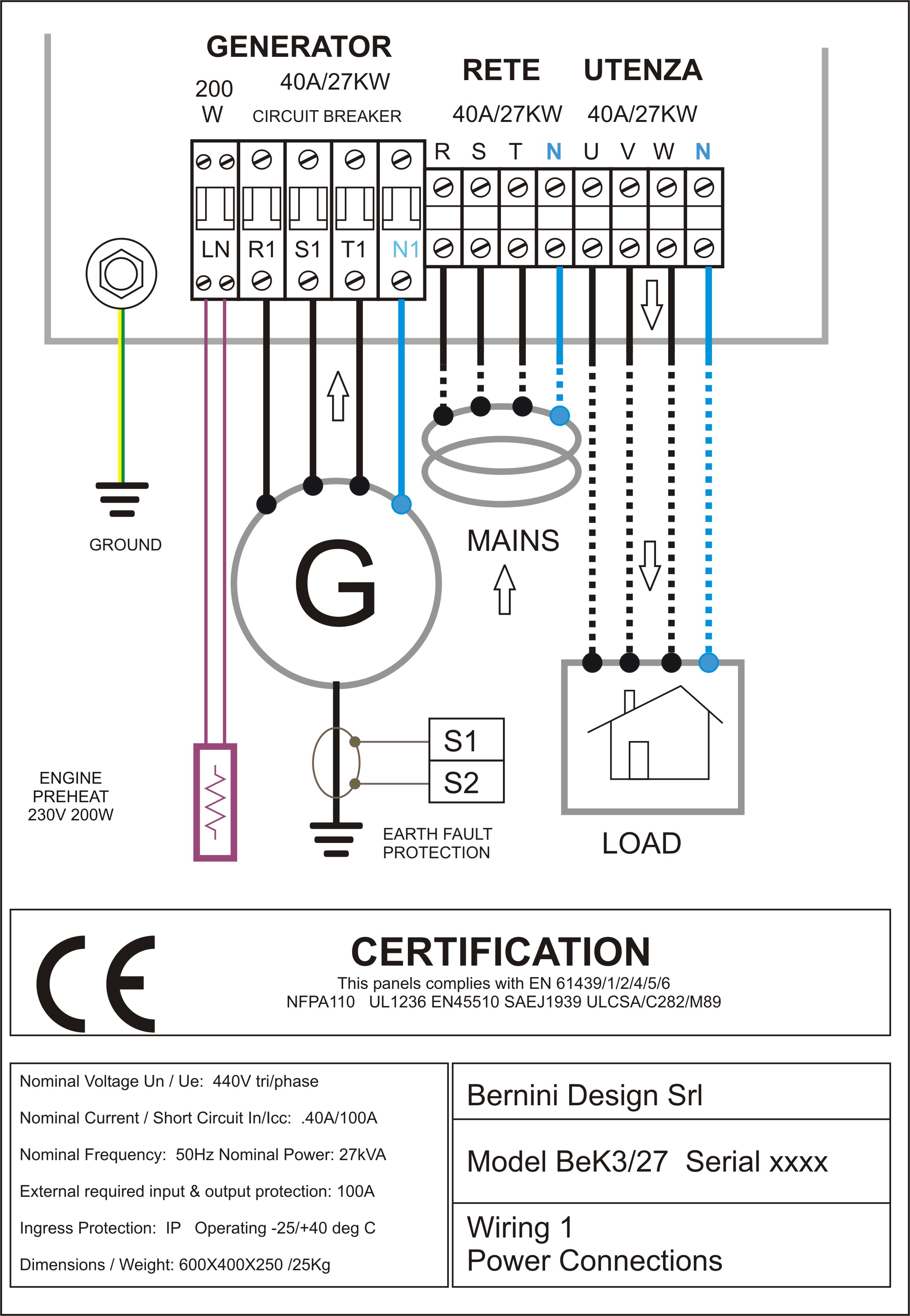
Refer to the appropriate wiring diagram as defined in table 3 based on your protection method and installation requirements. No cable box required.
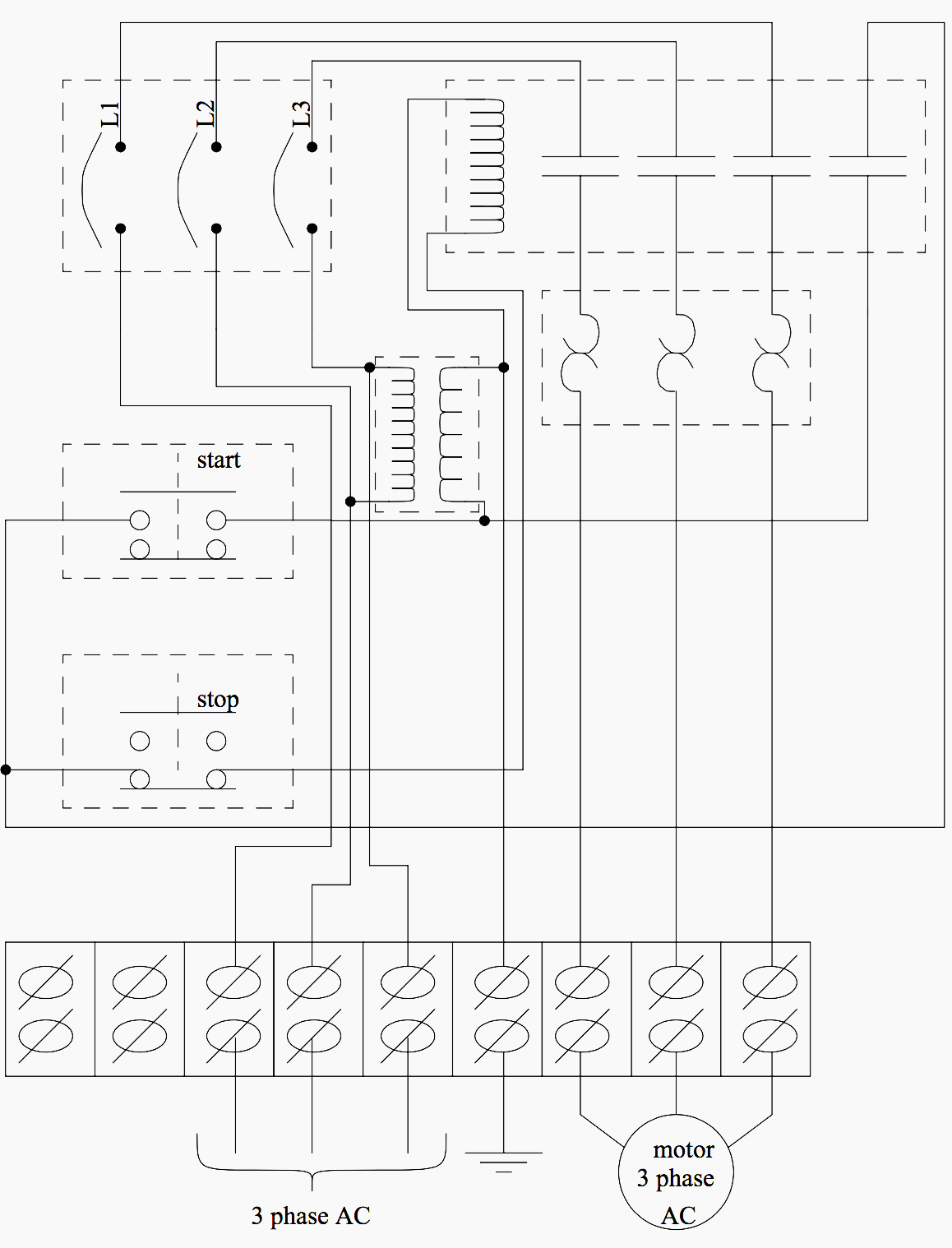
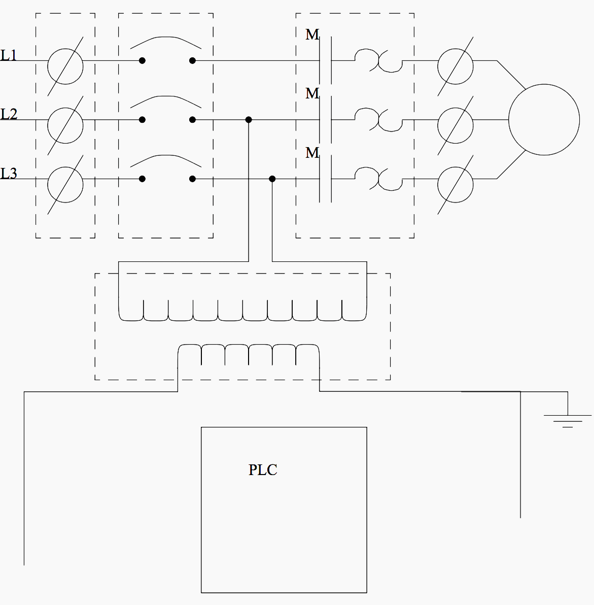
Basic Electrical Design Of A Plc Panel Wiring Diagrams Eep
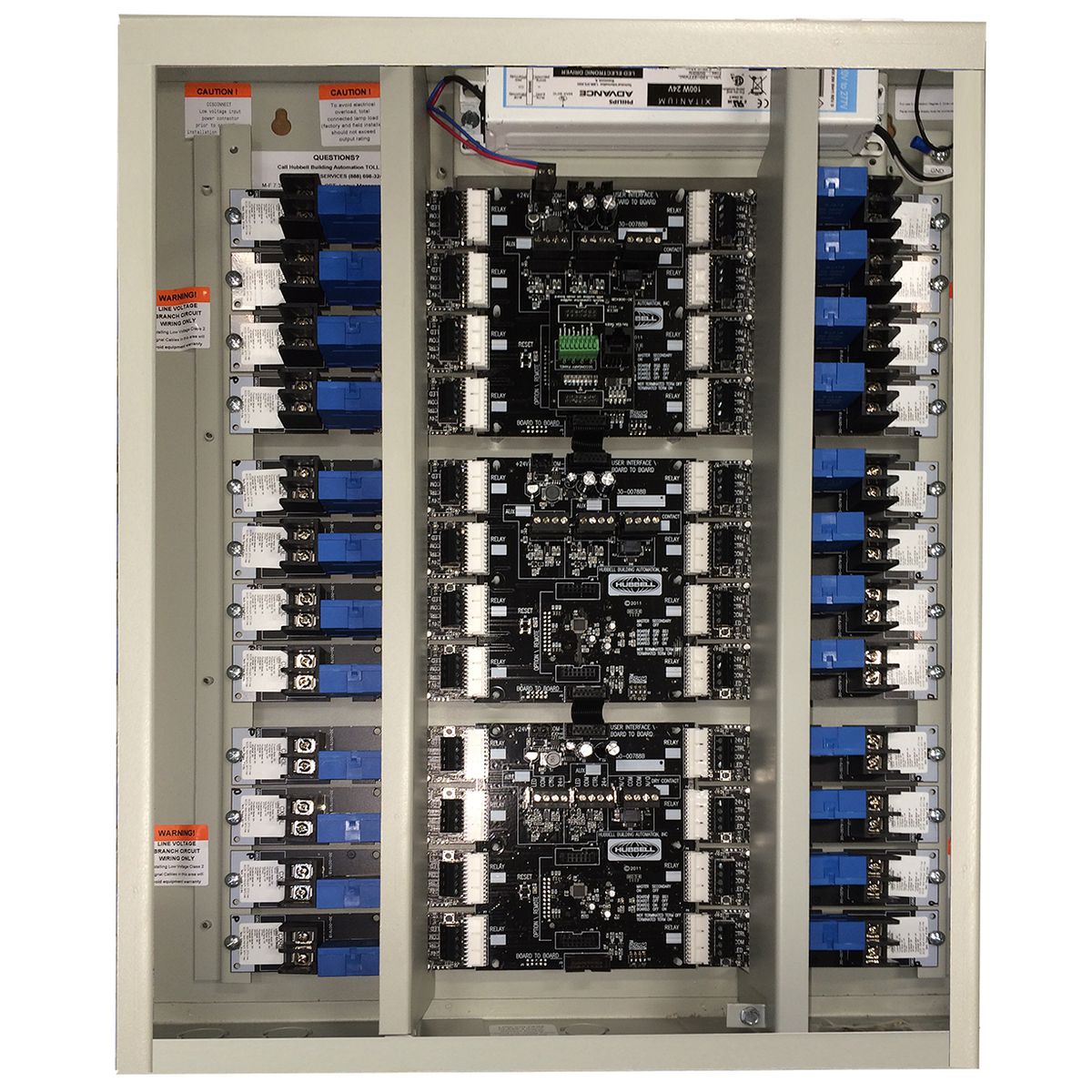
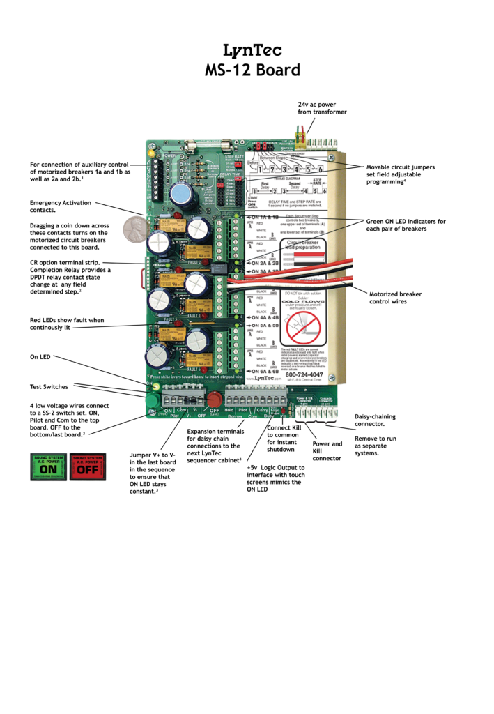
Lcp panel wiring diagram. Unlimited dvr storage. Wiring diagram nnoeesample wiring diagram for a lcpa model sample system topology ethernet dali dac 0 10 vdc dali dimmable ballast dali multi sensor 10 10 20 30 40. Lighting control panel lcp. How to wire an electrical panel square d duration. Ft feed through panel circuit breakers not included 3m or 3ml 1 phase 3 wire feed split phase 4m or 4ml 3 phase 4 wire feed lcp panel model numbers. Led 3wire continued lcp128 panel with dimming module lcp128 panel with adaptive dimming module lcp128 panel with adaptive dimming module dimmed for illustration purposes only.
Lighting control panel using contactor and relay what is a lighting control panel. A lighting control system is an intelligent network based lighting control solution that incorporates. Quantity and type prefix example lcp 2x2d1a8t 1204ml 20 voltage branch circuit breaker rating feed. Mini and standard size modules. Lcp panel wiring diagram. Live tv from 70 channels.
Installation of a lighting control system duration. Rene schaub 9531 views. Dali field relay dali relay panel dali dimming module dali wallstation scene 1 scene 3 scene 4 scene 2 central. The electrical design for each machine must include at least the following components. Preferred feed wiring entry for feed through panels is from the top or bottom left of the panel wired directly to module terminal blocks. Tuwire fluorescent lcp128 spec grade panel tuwire ballast tuwire tu.
162 awg recommended wire. Also refer to figure 4 for lcp100 switch setting terminal connections and label details and information as well as dvc6200 sis terminal box details. Battle of the tools 2833999 views. Consult model number pages for specific voltage and capacity information.
