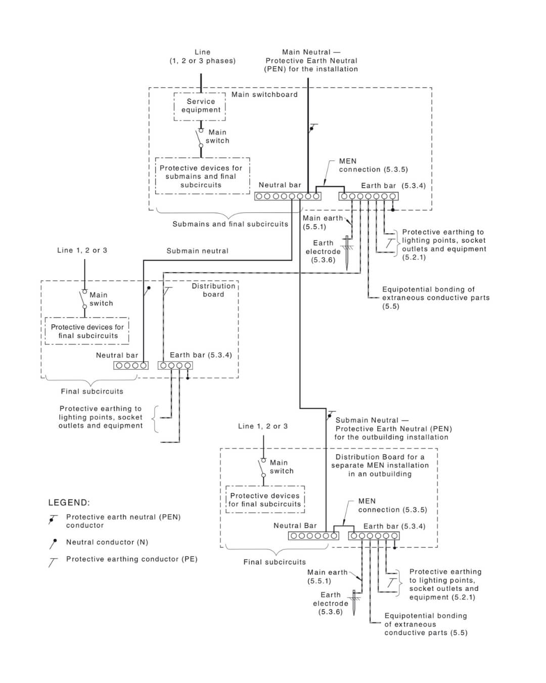
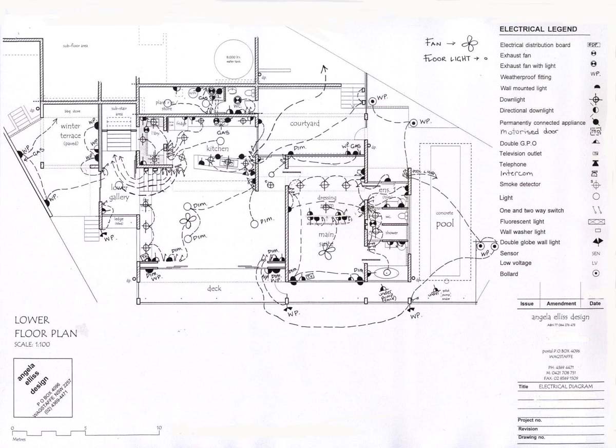
It shows how the electrical wires are interconnected and can also show where fixtures and components may be connected to the system. From there power is routed to the individual circuit breakers and safety switches for the different light and power circuits in your home.

Clarification Changes To Generator Installations
Australian switchboard wiring diagram. About the type of construction methods used. Domestic switchboard wiring diagram australia home wiring diagram. Phase 1 red phase 2 white phase 3 dark blue neutral black earth green. A wiring diagram is a simple visual representation of the physical connections and physical layout of an electrical system or circuit. A wiring diagram is a simple visual representation of the physical connections and physical layout of an electrical system or circuit. It shows how the electrical wires are interconnected and can also show where fixtures and components may be connected to the system.
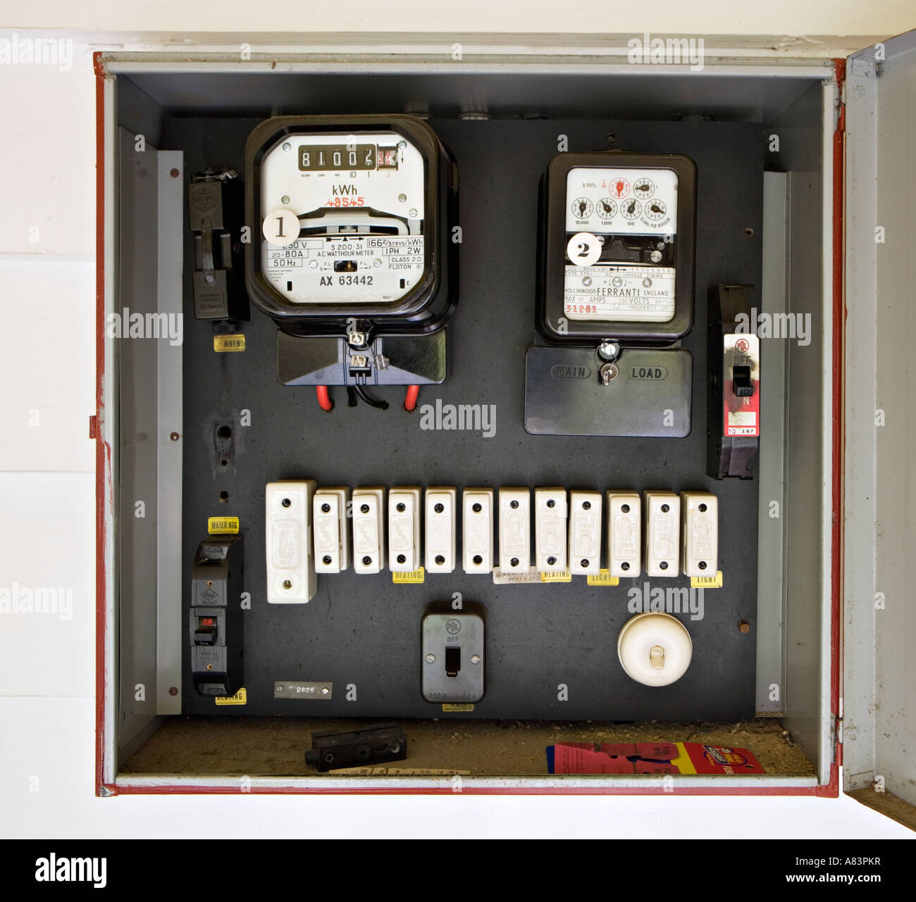
A service fuse connects the supply to the switchboard switch box with its power meter and main switch. In this single phase home supply wiring diagram the main supply single phase live red wire and neutral black wire comes from the secondary of the transformer 3 phase 4 wire star system to the single phase energy meter note that single phase supply is 230v ac and 120v ac in usthese two lines line and neutral from energy meter are. How to wire rcd residual current device. A final sub circuit is a circuit from a switchboard to which only consuming devices or points are connected. The list below also outlines the different colour codes for single phase and multiphase in australia. The diagram shows you the standard type of electrical wiring known as men multiple earth neutral.
Installation wiring also known as building wiring is for things such as the wiring behind power points and walls. These methods will. Old australian colour code multiphase. Learning notes final sub circuits. Before selecting a wiring system for an installation you need to know something.


