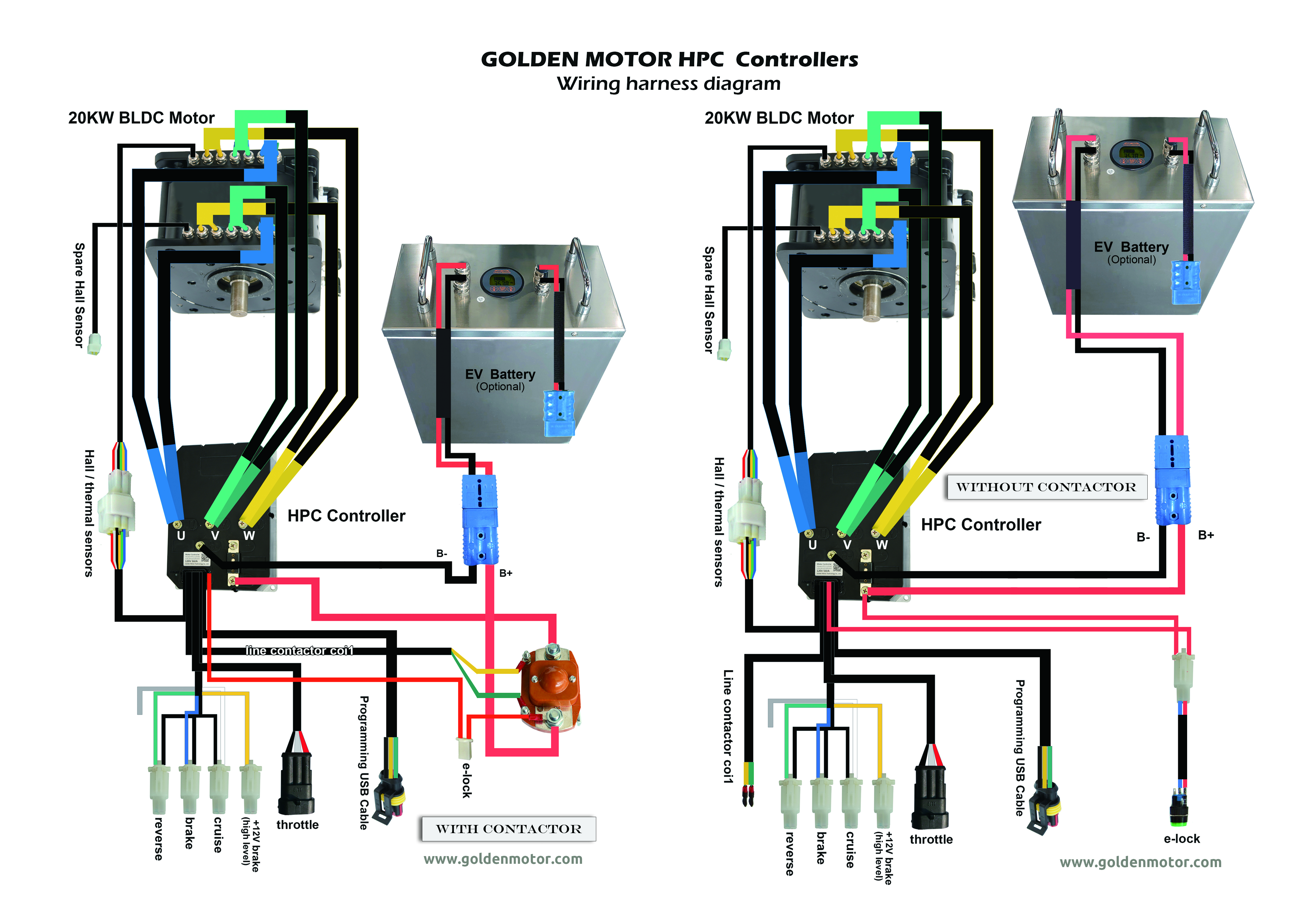
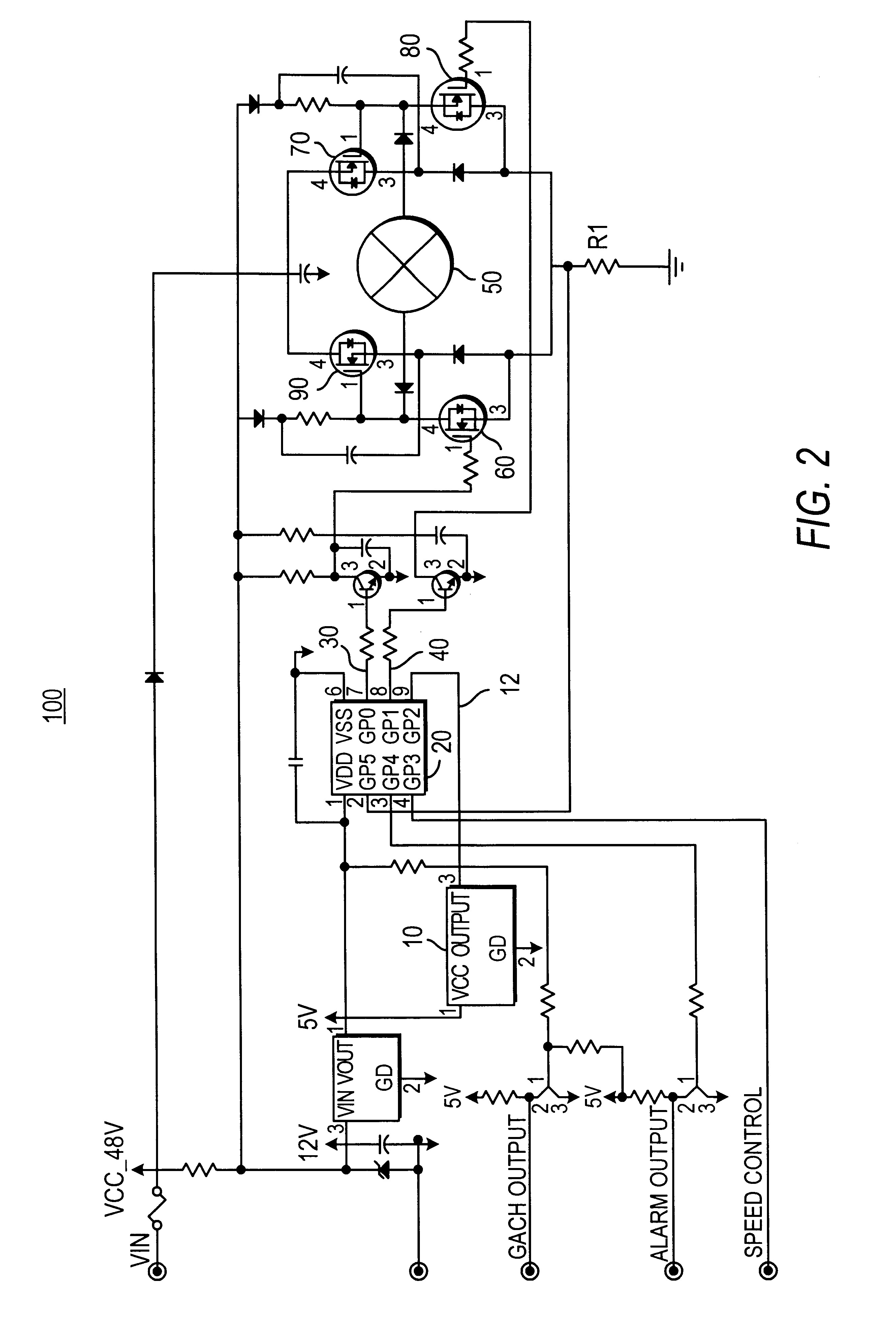
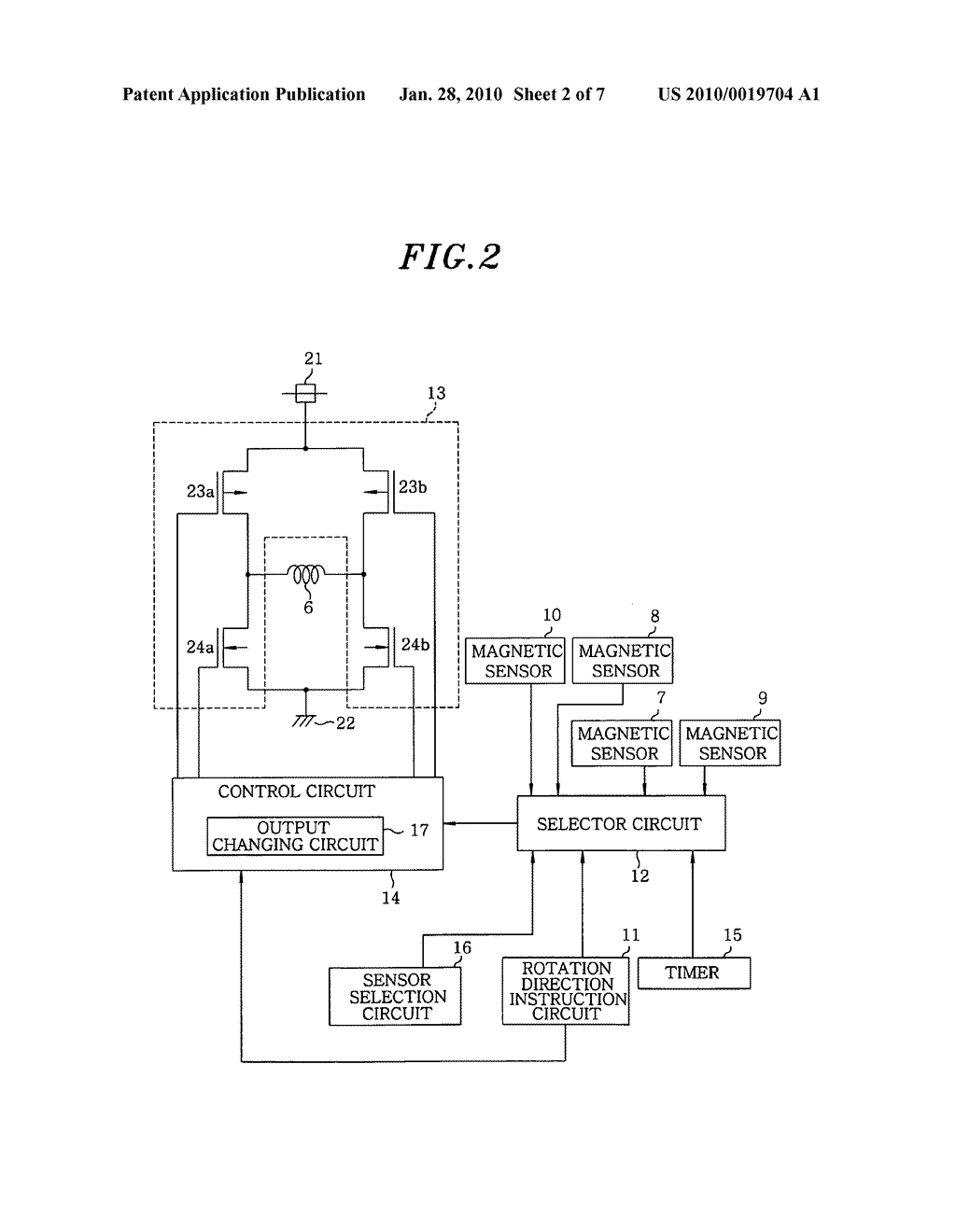
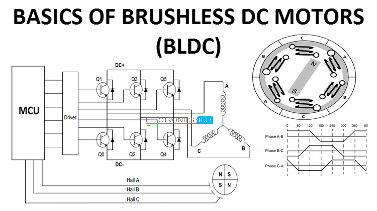
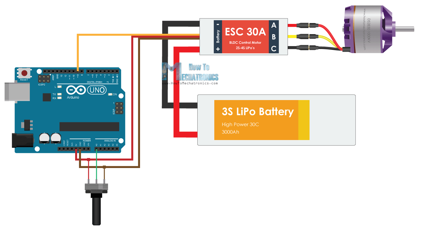
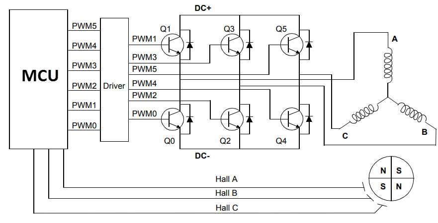
Brushless dc controllers mdc wiring diagram data schema from brushless motor wiring diagram sourceinboxmeco rc motor and esc wiring schematics wiring diagrams from brushless motor wiring diagram sourceseniorlivinguniversityco. One common setup is called the full bridge drive circuit.
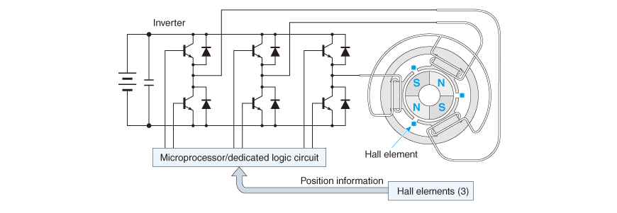
1 3 2 Brushless Dc Motor Nidec Corporation
Brushless dc motor wiring diagram. How to find wire functions of bldc controller which dont have labels on wires. Block diagram of a typical brushless dc motor control or drive system is shown in the following image. A brushless motor is constructed with a per manent magnet rotor and wire wound stator poles. This replaces the conventional mechanics comprised of brushes rubbing on the commutator to energize the windings in the armature of a dc motor. The brushless dc bldc motors increasing popularity is due to the use of electronic commutation. Brushless dc motors bldc have been a much focused area for numerous motor manufacturers as these motors are increasingly the preferred choice in many applications especially in the field of motor control technology.
With the advent of cheap computers and power transistors it became possible to turn the motor inside out and eliminate the brushesin a brushless dc motor bldc you put the permanent magnets on the rotor and you move the electromagnets to the stator. Bldc motors are superior to brushed dc motors in many ways such as ability to operate at high speeds high efficiency and better heat dissipation. By plug i mean the diagram that describes what each of the wires coming out. Then you use a computer connected to high power transistors to charge up the electromagnets as the shaft turns. Brushless dc motors were made possible by the development of solid state electronics in the 1960s. Brushed dc motors were invented in the 19th century and are common.
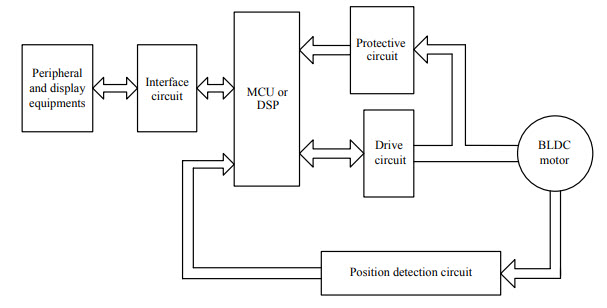
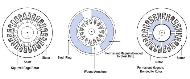
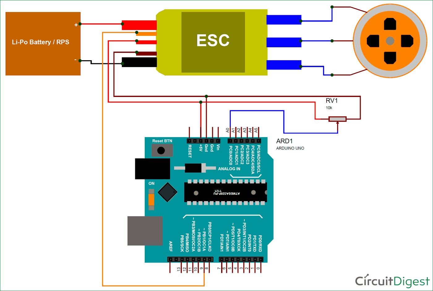
Motor control part 1. Figure 1 is a simplified illustration of bldc motor con struction. Ebike brushless motor controller identification of wires. An electric motor develops torque by alternating the polarity of rotating magnets attached to the rotor the rotating part of the machine and stationary magnets on the stator which surrounds the rotor. The 48v w brushless dc tricycle motor main specification. This drive circuitry is often known as electronic speed controller system or simply an esc.
Unfortunately this one hasnt come with any wiring diagram. Electrical energy is converted to mechanical energy by the magnetic attractive forces between the permanent magnet rotor and a rotating magnetic field induced in the wound stator poles. An introduction to brushless dc motors duration.



.png)

