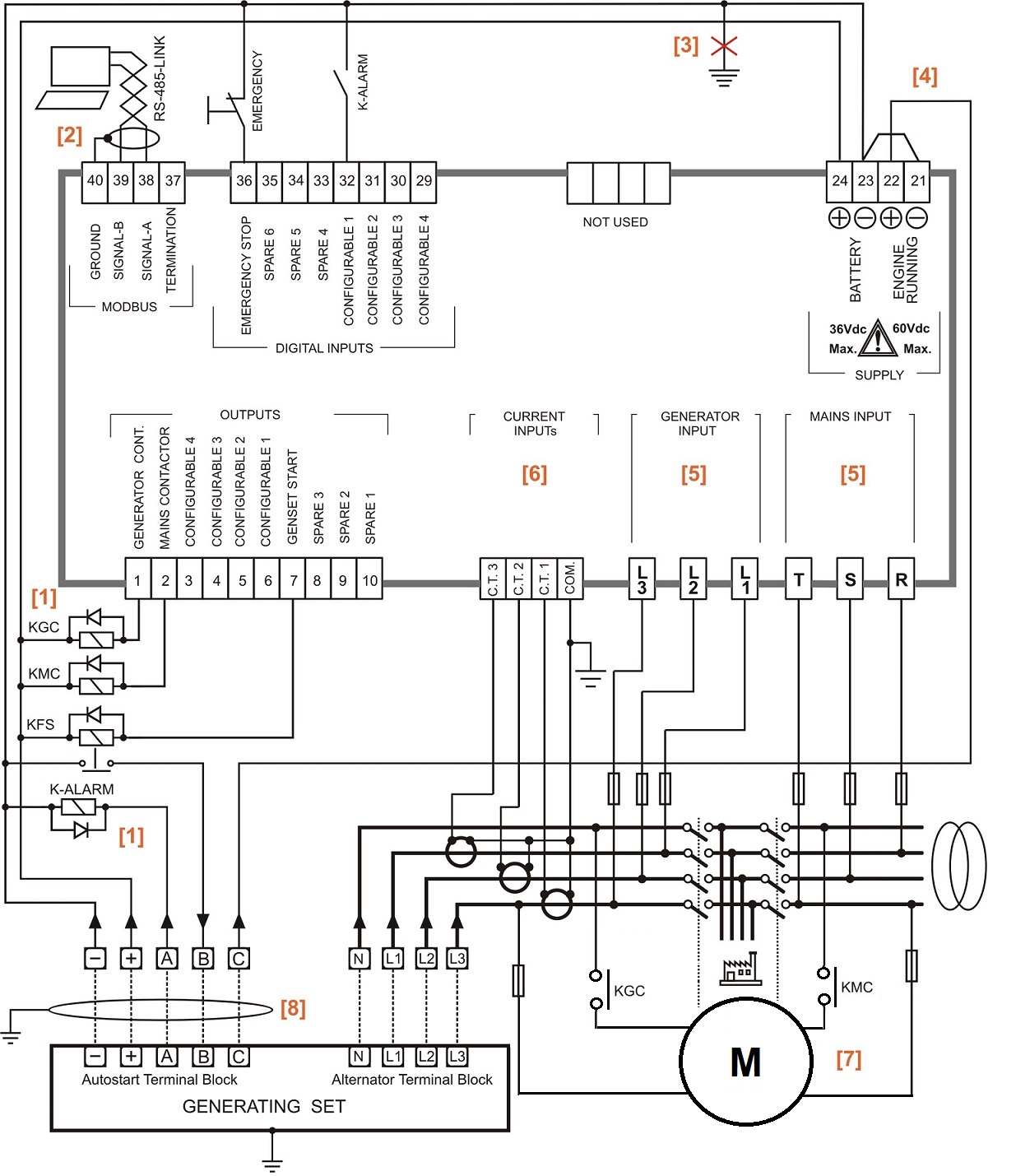
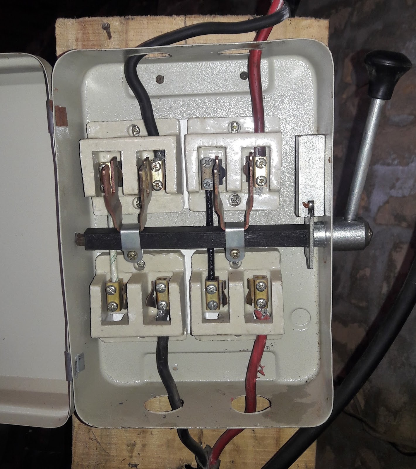
The upper portion of the changeover switch is directly connected to the main power supply while the lower first and right connections slots are connected to the backup power supply like generator or inverter. In our previous ups inverter wiring diagrams connections for home we show that how to wire and connect an automatic ups and batteries to the home distribution board for continues power supply.

02807d8 Change Over Switch Wiring Diagram Wiring Resources
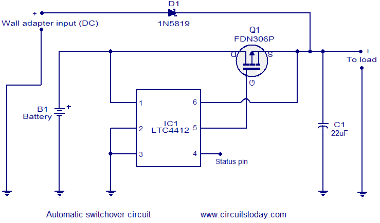
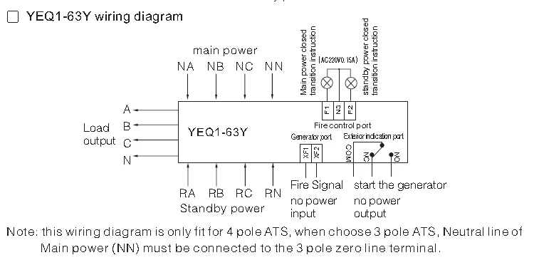
Change over switch wiring diagram. In the above manual changeover switch wiring diagram i shown the incoming supply from the energy meter incoming supply form the portable generator and out going supply to load or house load. In fig 2 different connection and wiring diagrams are shown for a two pole single phase manual changeover switch. In which i done all the connection. This circuit can be used for the automatic switchover of a load between a battery and a wall adapterltc4412 controls an external p channel mosfet to create a near ideal diode function for power switch over and load sharing. How to do manual auto ups inverter wiring with changeover ats switch. Note that this diagram is about the manual handle type change over switch and in sha allah soon i will make a diagram about the rotary type change over switch wiring diagram for single phase three phases and three phase four wire system.
In the diagram i shown handle type manual changeover switch. The circuit diagram shown here is of a automatic changeover switch using ic ltc4412 from linear technologies. 3 phase manual changeover switch wiring diagram for generator with complete installation guide the 3 phase. In today ups inverter installation tutorial we will show how to connect and install the battery backup power through.


