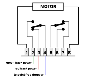
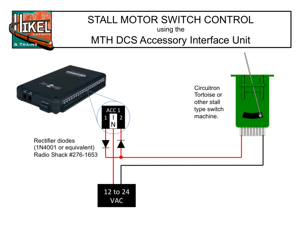
The circuitron r emote t ortoise m ount consists of a molded base mechanism to which the tortoise not incl uded is mounted. A thin precise laser cut plastic template for use when multiple tortoise switch this thin wire attaches to a compact actuator mechanism and is mounted.

Another Tortoise Wiring Question Model Railroader Magazine
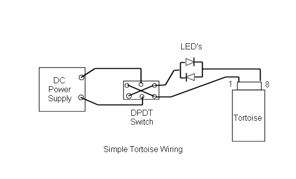
Circuitron tortoise wiring diagram. It shows the components of the circuit as simplified shapes and the faculty and signal friends together with the devices. I built a control panel with a track diagram and a miniature dpdt at a typical turnout y. For my 20 code 83 turnouts i used tortoises. I also give a brief description of the power requirements and show the wiring. Circuitron can be reached at 815 886 9010. Start with the tortoise fulcrum near its maximum throw adjustment.
They provide further clarification and in some cases wiring diagrams of 01 or referring to notes specific to the ar 1 and tortoise. If you clean the sub. Apply heavy duty foam double sided tape to the top of the tortoise red piece in photo. My supply is from circuitron and can handle 30 tortoises. The hole above the bright screw needs to be opened with a 60 drill 0040 inch. 20 ma ideal to power led in series with tortoise use pcb edge connectors to wire tortoise.
In this episode of how its done we will see how to make a wiring harness for the circuitron tortoise switch machine. An adjustable lever arm is fastened onto the tortoise output and drives a stainless steel wire inside a flexible teflon tube much like a sub miniature choke cable. Thanks to steve at circuitron for furnishing this info. Tortoise wire bending guide. Wiring diagram september 02 2019 1619 circuitron tortoise wiring diagram tortoise circuitron tortoise wiring diagram wiring diagram is a simplified agreeable pictorial representation of an electrical circuit. My diagram just shows 6 contact for red and 7 for green.
Wiring panel leds in series with the tortoise switch machine green led irzziaa 271 rocbaar drive romeoville il 60446 815 886 9010 12345678 note. Do not use additional resistors. This thin wire attaches to a compact actuator mechanism and is mounted beneath the turnout. Panel lights signals see diagram 4 above or request application note an 6000 07 for more detailed wiring diagrams although the auxiliary contacts on the tortoise may be used to power panel lamps or signals the low current draw or the tortoise allows you to wire light emitting diodes leds directly in series with the motor. The resistance of the tortoise motor is about 600 ohms an ideal limiting resistance for leds. The fulcrum hole is just fine.
Circuitron tortoise wiring diagram. Off center mounting of the tortoise an 6000 01 switch point and signal wiring using the internal switches on the tortoise switch machine an 6000 02 using the tortoise with peco turnouts an 6000 03 edge connectors for use with the tortoise an 6000 04. All the turnouts are powered by a single walwart type 12v power supply split to the dpdts at barrier strips for each connection.


