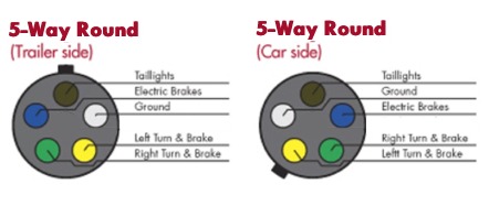
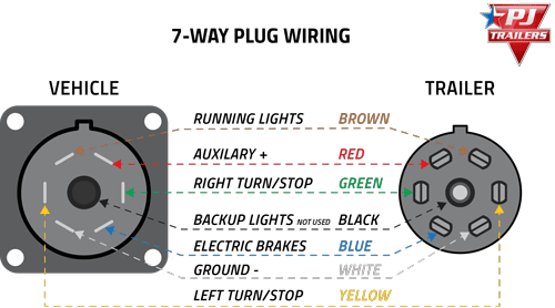
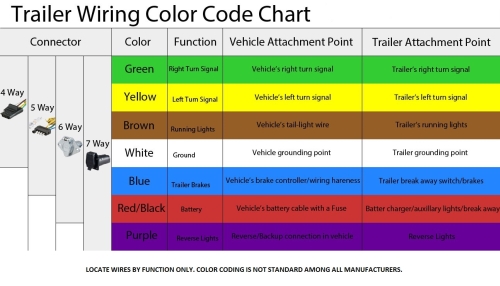
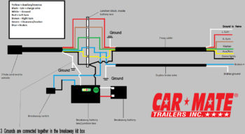
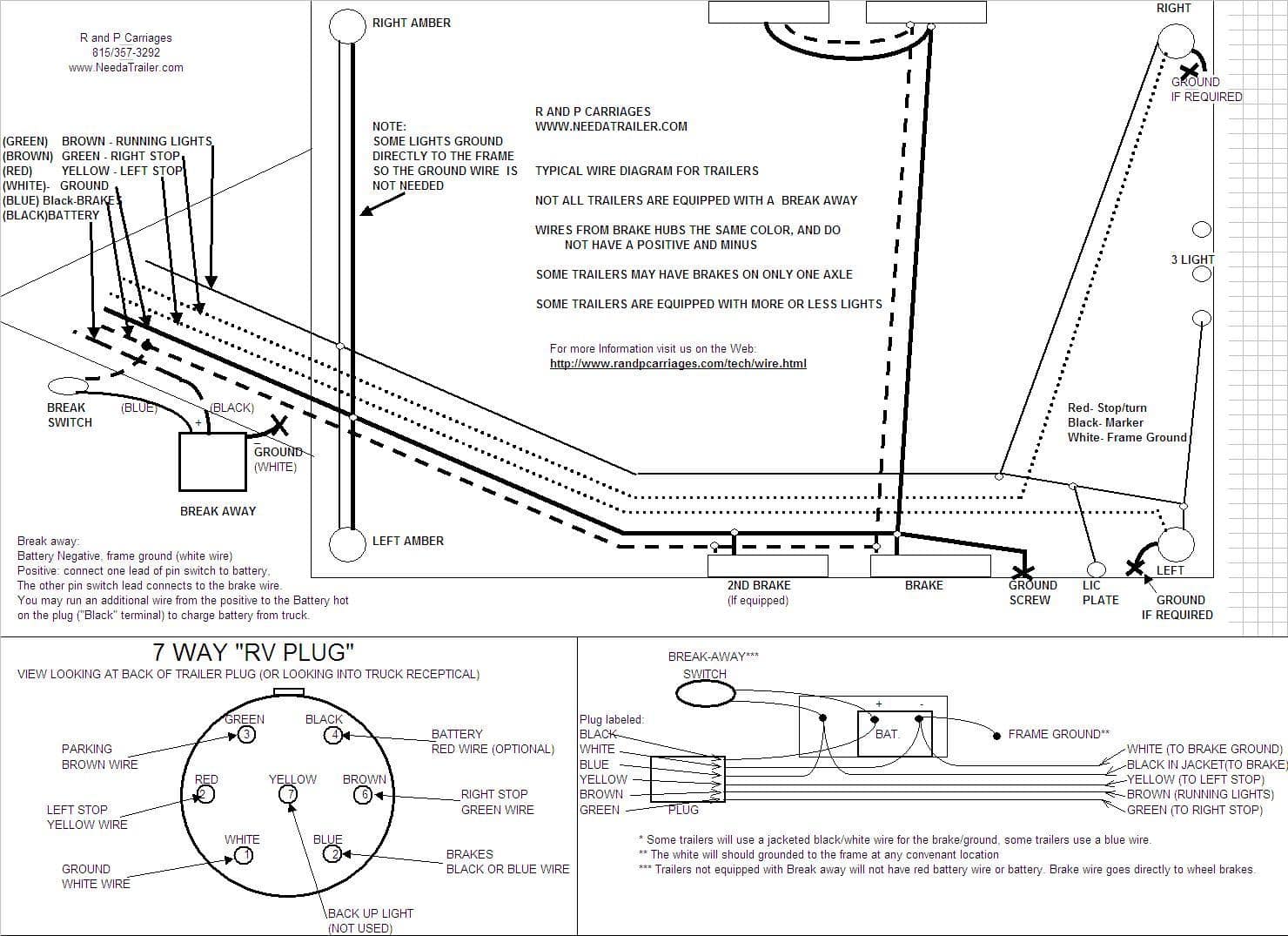
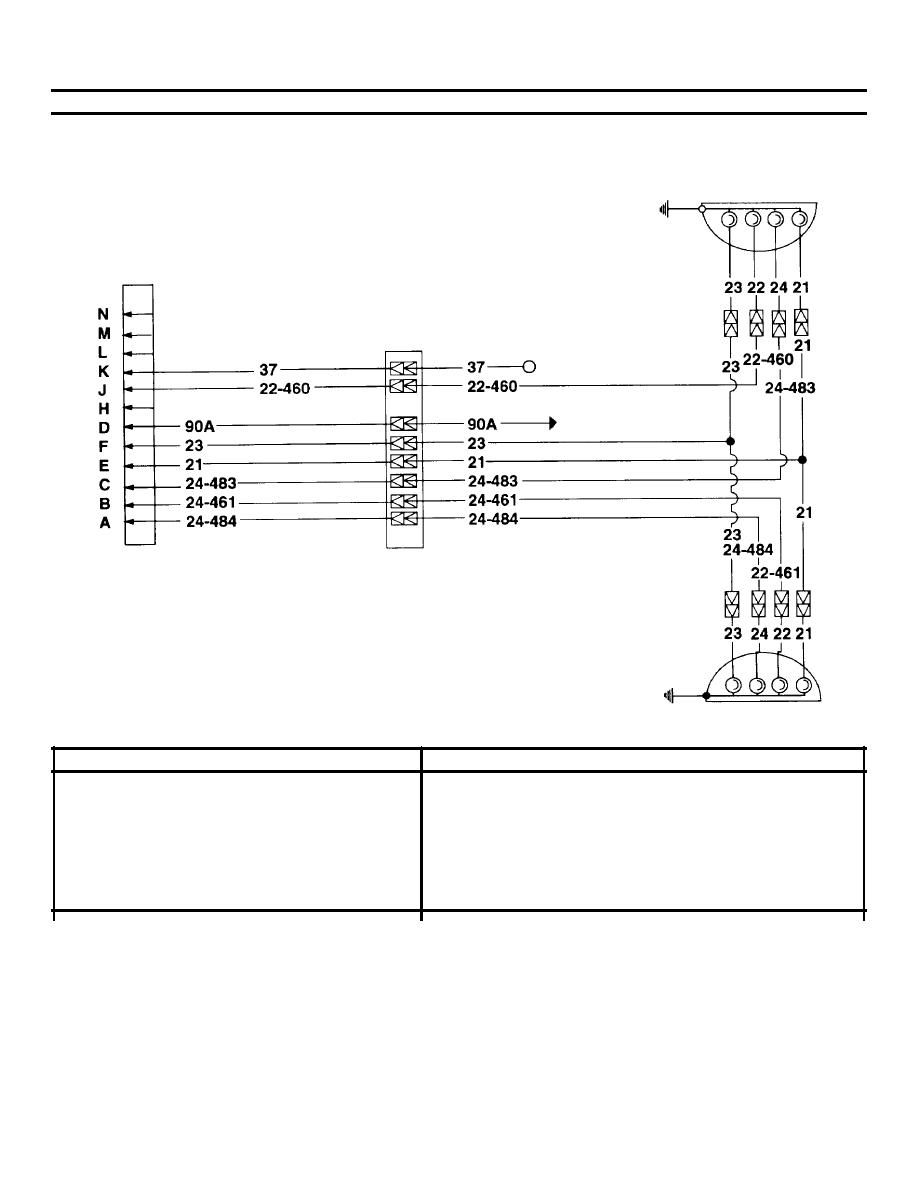
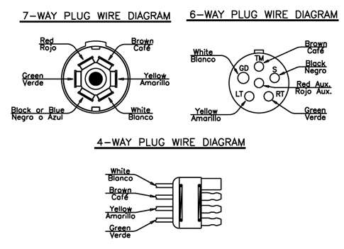
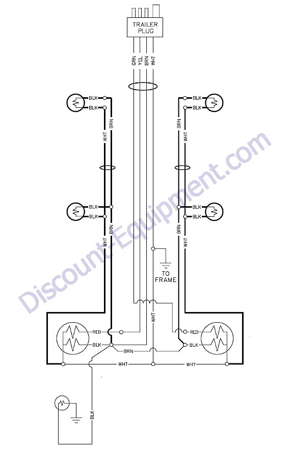
6 way connectors include the basic connection of. Typical trailer wiring diagram and schematic.
Trailer Sauce Lights Amp Wiring
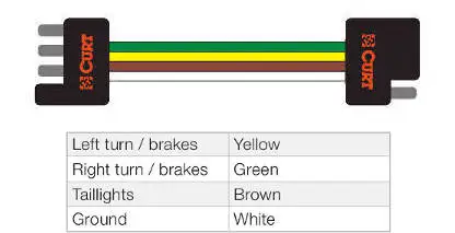
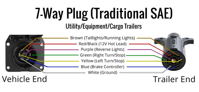
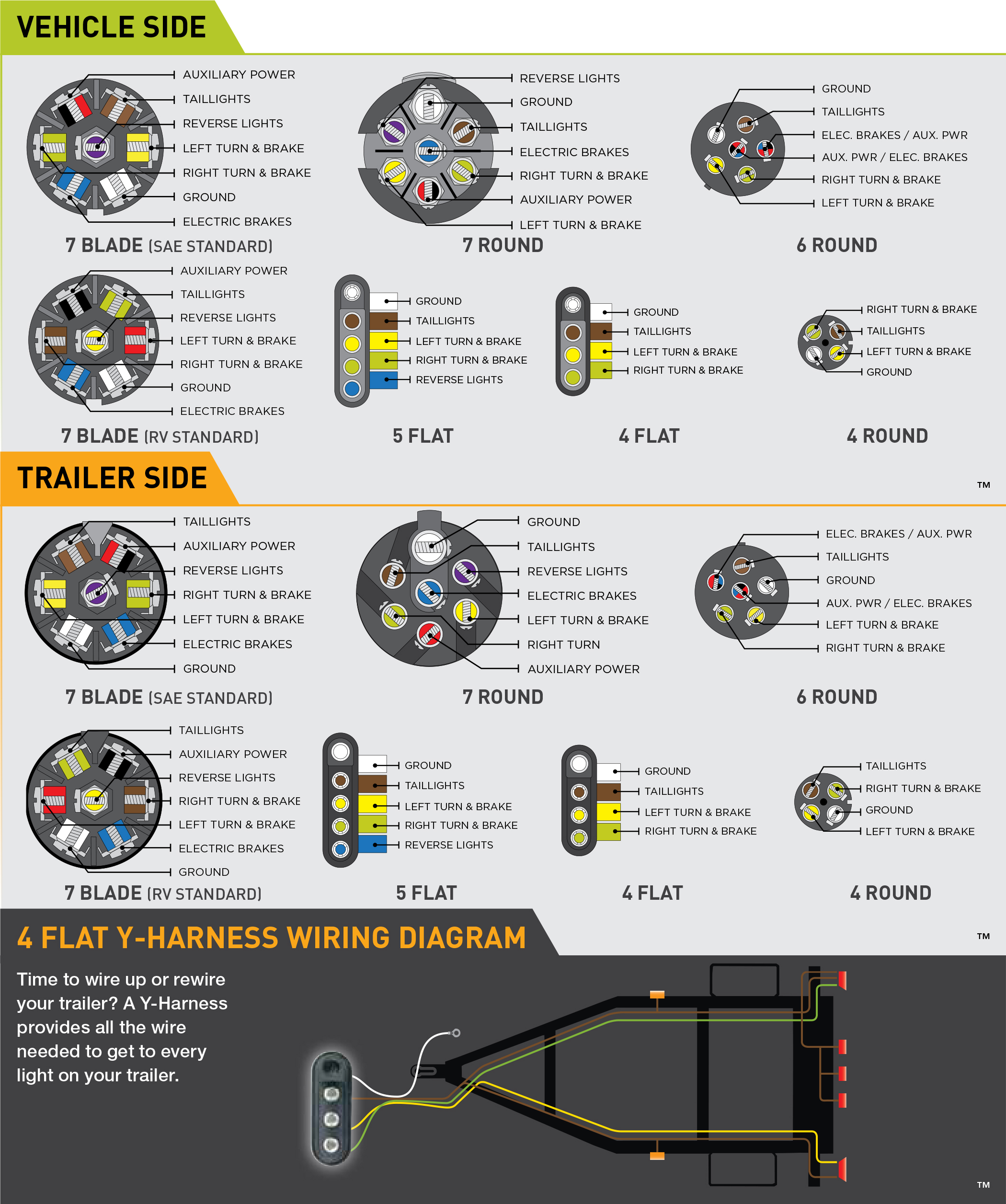
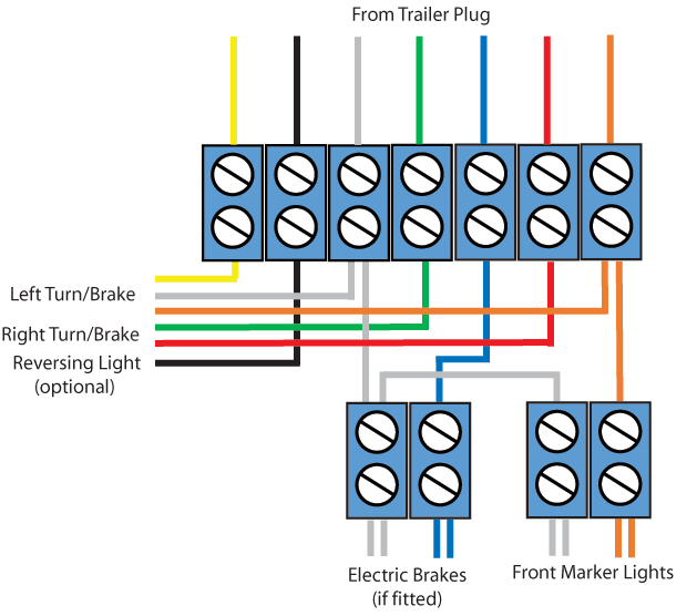
Equipment trailer wiring diagram. Trailer wiring diagrams trailer wiring connectors various connectors are available from four to seven pins that allow for the transfer of power for the lighting as well as auxiliary functions such as an electric trailer brake controller backup lights or a 12v power supply for a winch or interior. Above we have describes the main types of trailer wiring diagrams. The use of an electrical circuit tester is recommended to ensure proper match of vehicles wiring to the trailers wiring. These 2 wire diagrams fit the needs for most trailers. Standard wiring pictured below viewed from the rear of connector where wires attach. Standard electrical connector wiring diagram.
Extrapolate the same expansion for additional axles. Trailer wiring diagram to connect the electric system of your trailer to the vehicle you will be using special connector. Eliminate hours of frustration by using our trailer testing equipment and quickly identify problems in the wiring of the trailer. Only the blue brake and white ground wires are different. Not all trailersvehicles are wired to this standard. If youre looking to replace the wiring on your trailer check out our trailer rewiring guide.
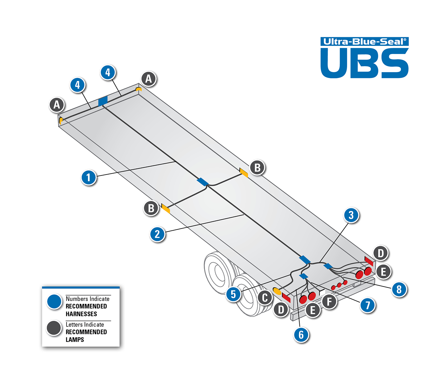
6 way trailer connectors 6 way trailer connectors are often used on gooseneck trailers but can be used for other types such as utility boat trailers and 5th wheels. Below is the generic schematic of how the wiring goes. The image above shows a single axle trailer and the next image shows wiring for tandem axles. Complete with a color coded trailer wiring diagram of each plug type this guide walks through each available solution including custom wiring splice in wiring and replacement wiring.
