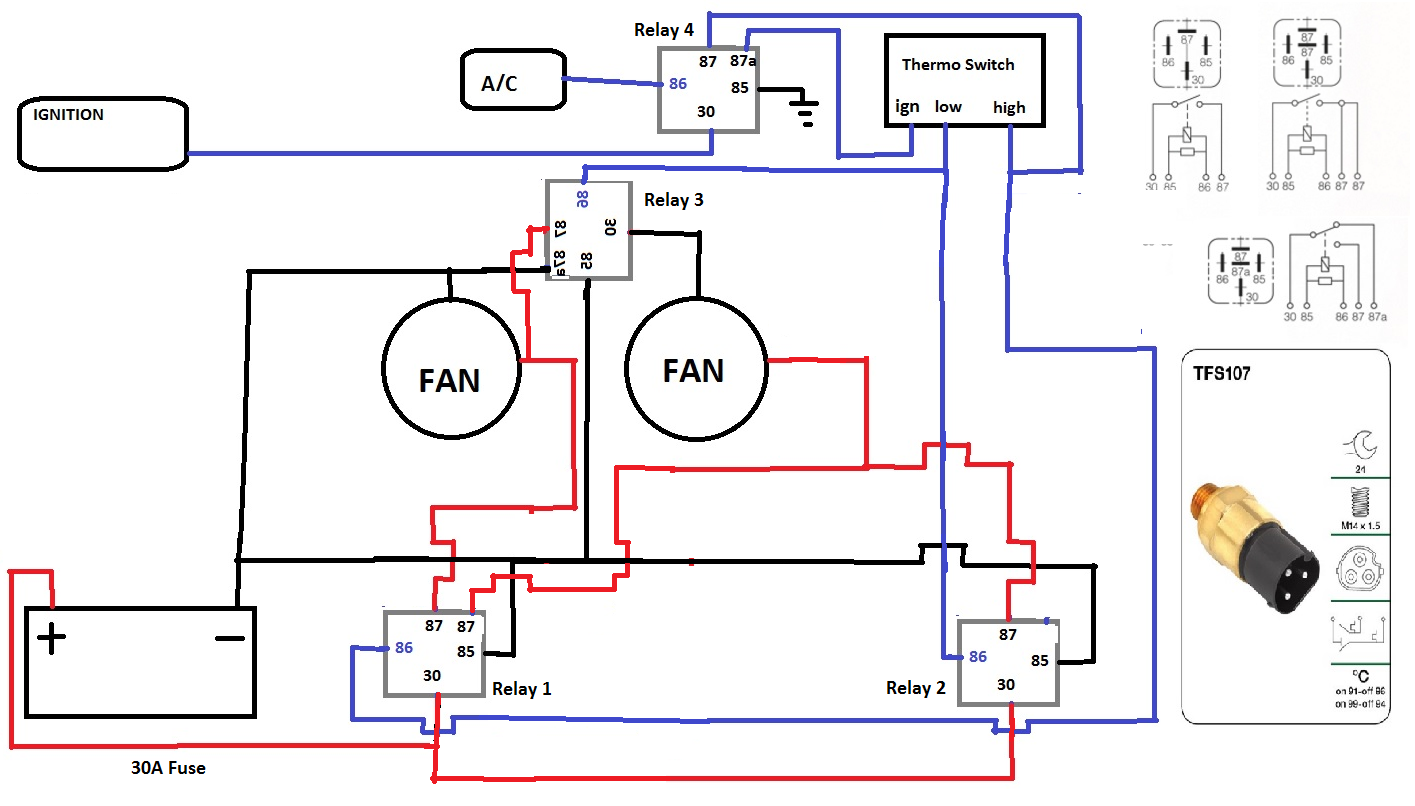
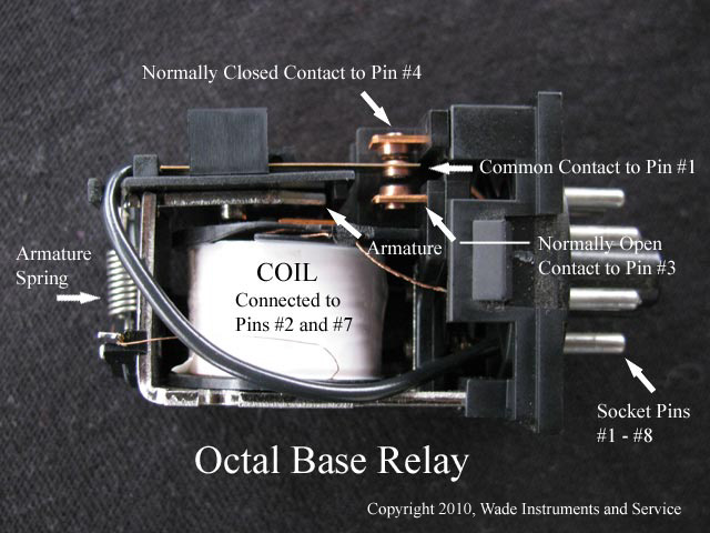
The interior mounted switch only draws minimal power though the interior fuse block to activate the relay. 24vdc coil relay schematic arduino sla 24vdc sl c datasheet songle relay download how to use relay with schematic of relay circuit diagram relay catalogue schrack 24vac relays rs components finder relays general technical information relays omron americas srd 05vdc sl c datasheet srd relay songle 12 volt relay wiring diagram free wiring diagram.

Wiring Interposing Relays Acc Automation
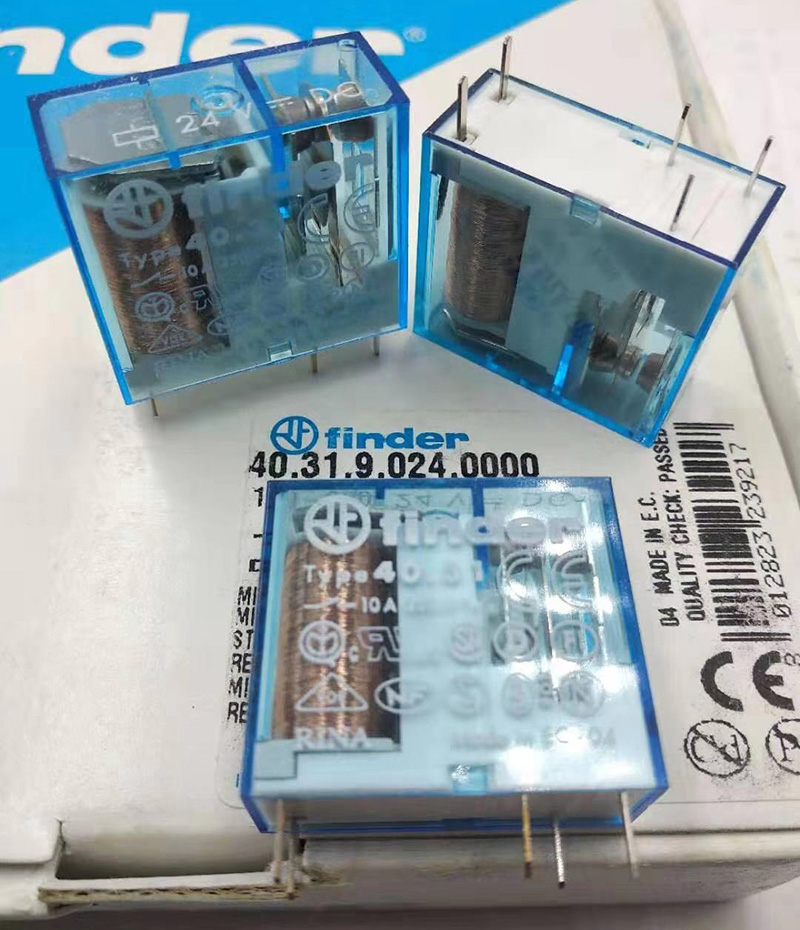
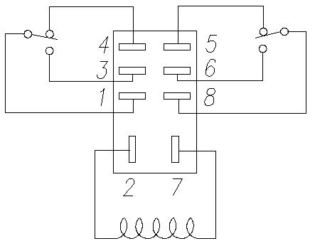
Finder 24vdc relay wiring diagram. This pinout image is only a 2 pole diagram for room on the page purposes but you can get the picture here with this one since a 3 pole will just have 1 more set of contacts. Wiring with a relay allows the power to run straight from the battery through the relay mounted nearby directly to the lights. The dual purpose finder test button can be used in two ways. Buy relays pigtails and kits here. Power relay for photovoltaic inverters. Type 02600 sealed construction 75 cm insulated flexible wire termination.
In this case when the test button is pushed the contacts operate. Assortment of 24vdc relay wiring diagram. 10 a general purpose relay. Dan richard fishing recommended for you. 1 2 pole relay range 4031 1 pole 10 a 35 mm pin pitch 4051 1 pole 10 a 5 mm pin pitch 4052 2 pole 8 a 5 mm pin pitch pcb mount direct or via pcb socket 35 mm rail mount via screw and screwless sockets dc coils standard or sensitive ac coils cadmium free contact material 8 mm 6 kv 1250 µs isolation. When the test button is released the contacts return to their.
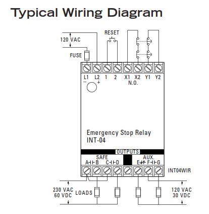
Same effect can be achieved by wiring two single contacts in series. See below for an example of a relay wiring diagram. Case 1 the plastic pip located directly above the test button remains intact. Example of wiring diagram of type 02600 this module is necessary when using between 1 and a maximum of 15 illuminated push buttons in the coil circuit each 15 ma max 230 v ac. The square relay pinout shows how the relay socket is configured for wiring. Finder relays types 4591 56xx 0300 62xx 0300 and.
Finder relay duration. It must be connected in parallel to the coil of the relay see diagram. How to properly install wiring for a 24v minn kota trolling motor with a circuit breaker. A wiring diagram is a streamlined standard photographic representation of an electrical circuit. Dc coils with only 170 mw holding power contact gap 3 mm according to vde 0126 1 1 en 62109 1 en 62109 2 reinforced insulation between coil and contacts 15 mm gap between pcb and relay base. It shows the elements of the circuit as simplified forms and also the power as well as signal links between the devices.
پی ال سی وان. Interruption of a circuit without any specific requirements for distance or dielectric strength across the contact gap.
