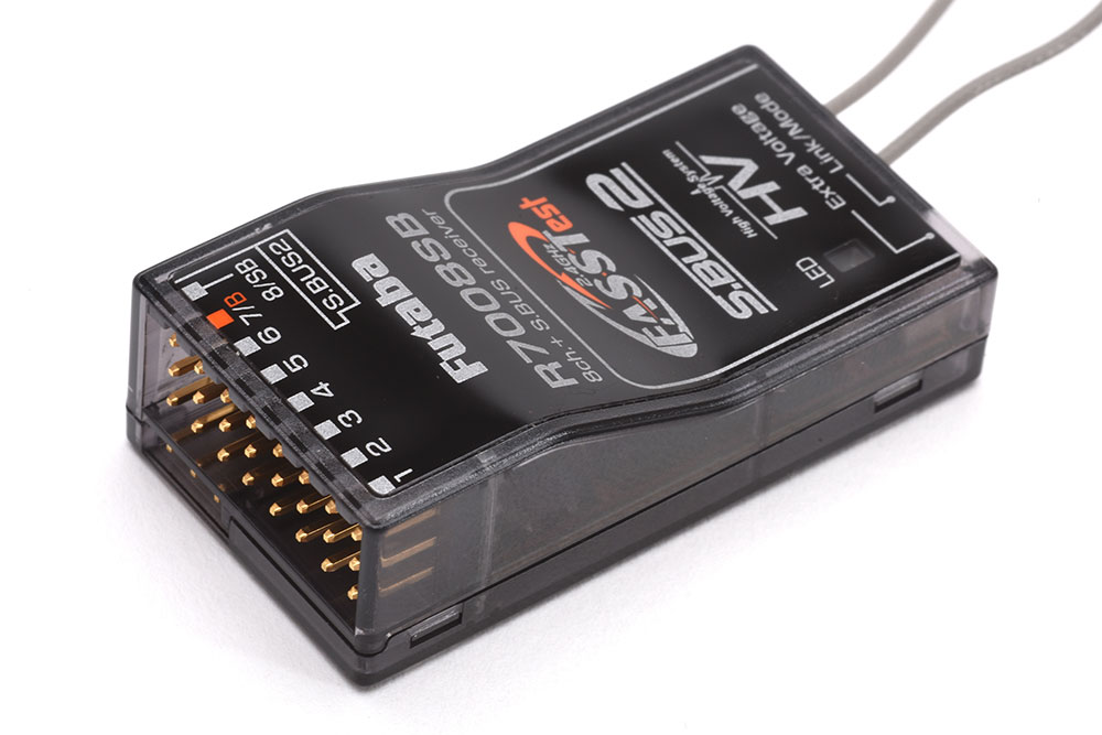
2 turn on the transmitter. As long as you are careful about polarity.

The Battery Eliminator Circuit
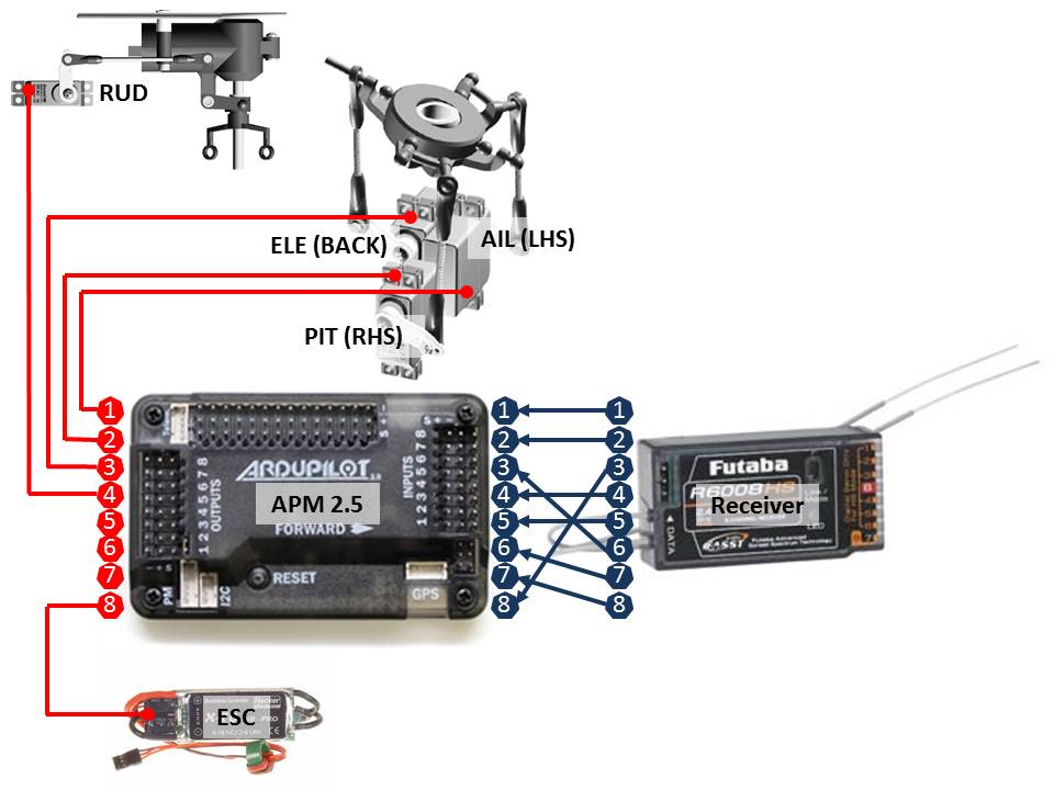
Futaba receiver wiring diagram. Futaba t6 ex ff 6 futaba t7 c ff 7 futaba t8 fg. 3 turn on the receiver. You can mix futaba servos with an airtronics receiver mix hitec jr servos with a futaba receiver etc. For futaba hitec and jr radio the servo and battery connections have the right polarity and signal wires although the connectors are physically different. 4 the receiver will wait for the linking process to begin for 2 seconds. Link button on the receiver.
Jr xg 14 xbus. Following that it will return to the normal operation mode. 1 close to each other within 20 inches half meter. 5 when the led of the. Futaba radio schematic wiring diagram database futaba corporation radio control web site radio systems for surface futaba corporation global website futaba service manuals and schematics fulltext search manuals futabausa futaba hack module how to in 5 minutes werhobbies radio control schematics. Place the transmitter into the receiver linking mode.
You can mix futaba servos with an airtronics receiver mix hitec jr servos with a futaba receiver etc. Graupner mx 16 hott. In futaba hitec and jr radio servos the servo and battery connections have the same polarity and signal wiring although the connectors are slightly different. Somewhere along the line the wiring didnt become compatible.


