C gas isolation and weep by pass valve assembly. Fan 1 out max 20amps 5.

Rm7840l1018 U
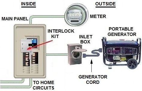
Gas interlock system wiring diagram. Normally closed common and normally open. The gasguard is ideal for when appliances are not fitted with flame failure devices or can be used to provide additional peace of mind when they are. Gas interlock system wiring diagram throughout gas solenoid valve wiring diagram by admin through the thousands of images on the web with regards to gas solenoid valve wiring diagram we choices the top choices together with ideal resolution exclusively for you and this photos is one among photos collections in your ideal photographs gallery regarding gas solenoid valve wiring diagram. 100 series gas ventilation interlock system installation guide 3 installation schematic basic install shown in kitchen mains rated wiring 2 core mains rated wiring 2core earth key panel air flow pressure switch repeat on fresh air make up fan if fitted always try to site in negative pressure to fire alarm panel if required. Merlin ct1250 gas interlock system troubleshooting guide ss northern ltd 5 ct1250 wiring diagram 1. Gas interlock system wiring diagram wiring diagram is a simplified conventional pictorial representation of an electrical circuit.
The gasguard gas proving system is designed to meet the requirements of igemup11 edition 2 for educational establishments and is a bs61732009 and igemup19 compliant ventilation interlock. Mains input 230vac 2. Volt free input 5. Remote em stop buttons and fire alarm input wired in series purchased separately. Ignition interlock wiring diagram collections of wiring diagram universal motor best ignition interlock wiring. The gas interlock system for commercial kitchens tel.
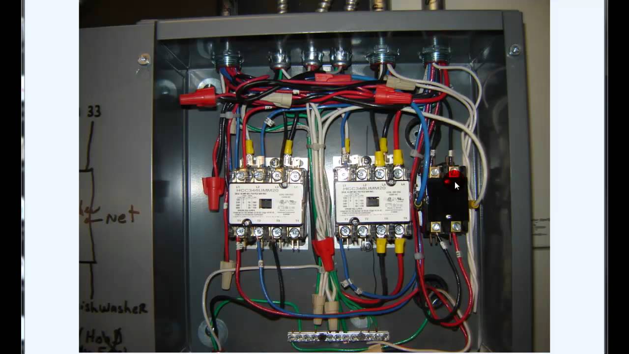
Fuse the 230vac power supply according to the fan currents 2a. Merlin ct1650 gas interlock system troubleshooting guide ss northern ltd 5 ct1650 wiring diagram 1. Ignition interlock wiring diagram beautiful unusual s13 redtop. Gas solenoid valve power output 230vac. Is a kind of schematic which utilizes abstract photographic signs to reveal all the interconnections of parts in a system. Electrical wiring layouts are made up of.
2 principle of operation the ventam 85 interlock gas proving system is comprised of three units. Fan 1 in max 20amps 4. It shows the components of the circuit as simplified shapes and the capacity and signal associates between the devices. Welcome to winnebago industries wiring diagrams. Please choose a year from the menu at left to start your search. To wiring diagrams provided as required.
A ventam 85 control panel. B fan air flow pressure switches. Connect as detailed in wiring diagram see section 11 gas valve. Gas solenoid valve power output 230vac. Connect 230vac gas solenoid valve as detailed in wiring diagram section. The ventam 85 panel is mounted in the kitchen where it is accessible and visible to the user.
Gallery of Gas Interlock System Wiring Diagram