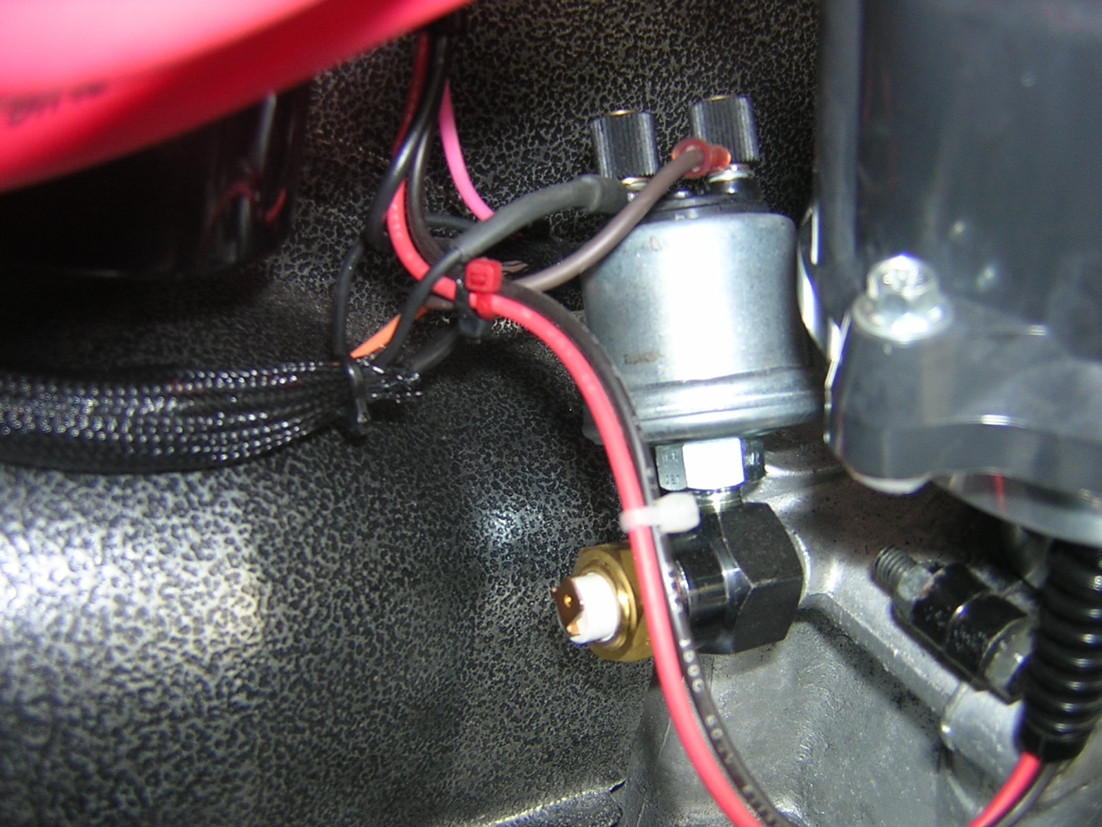
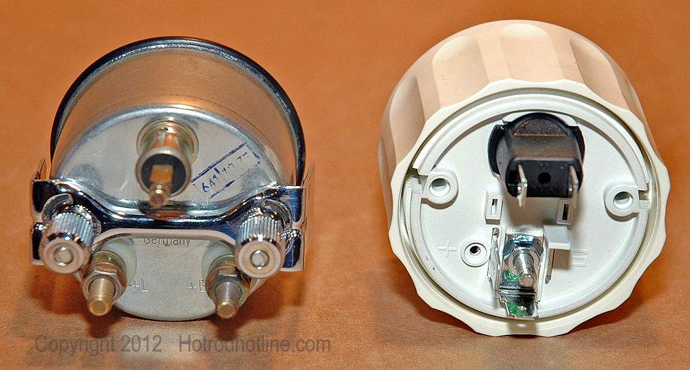
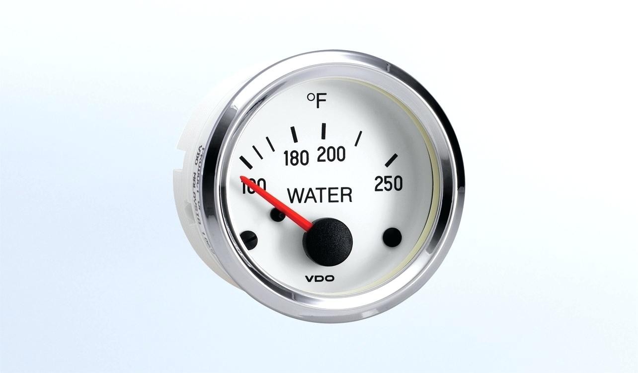
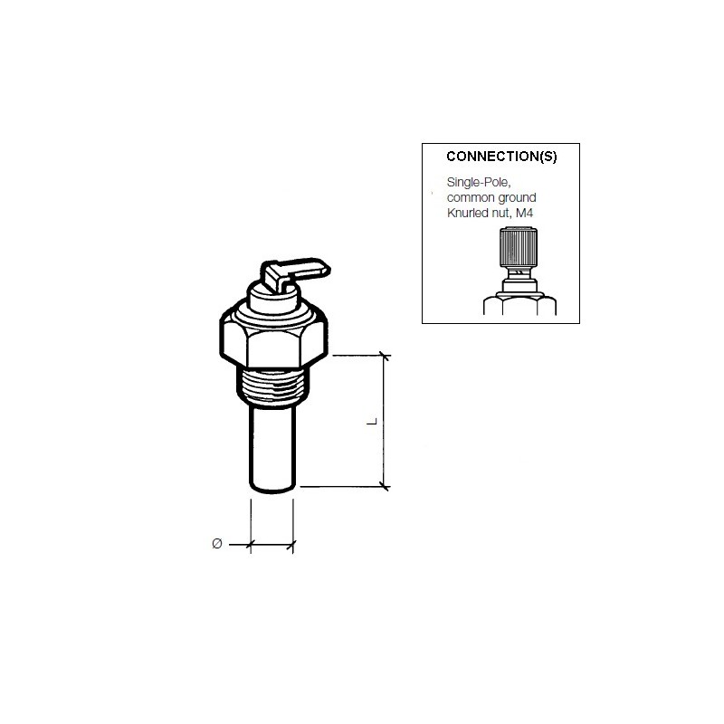
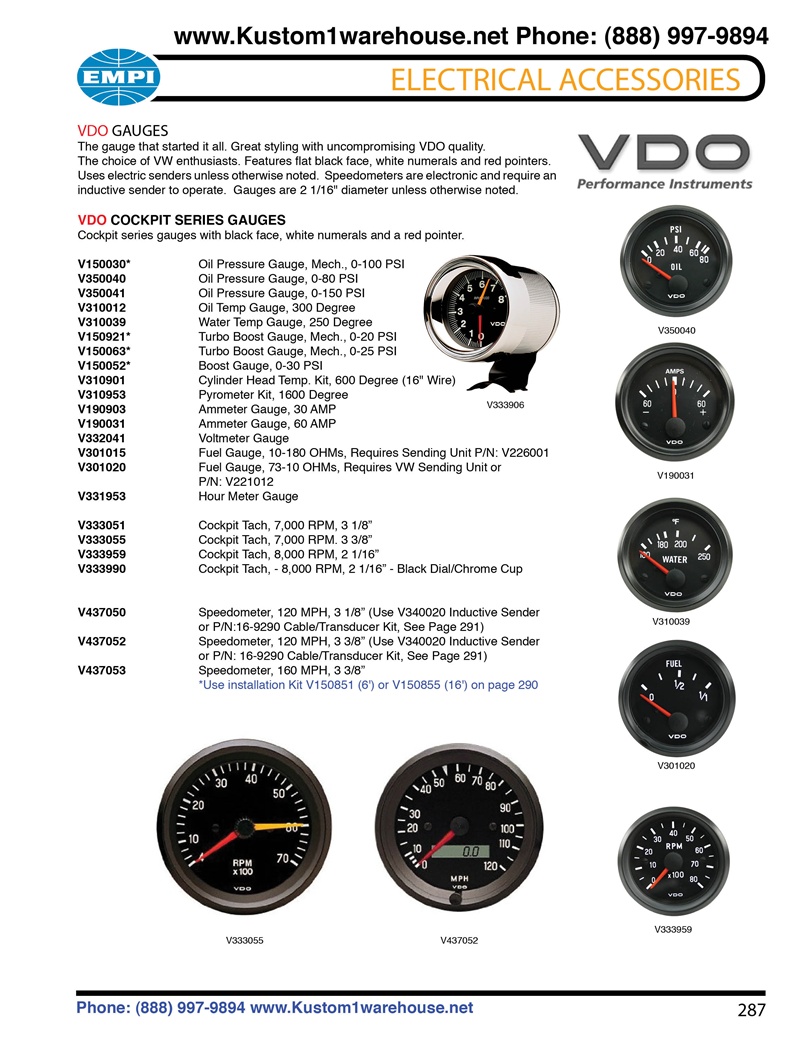
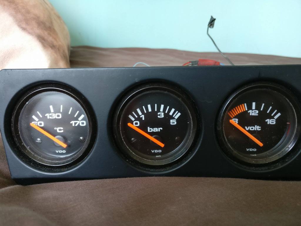
The final ground run using 14 gauge wire should be connected to a good. Fc water temperature gauge use with vdo sender 12v spade connection learn more viewline ivory fc water temperature gauge 1224v.
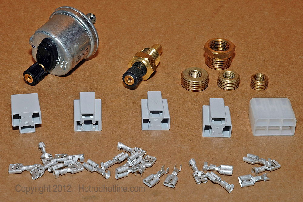
Updating To An Electrical Gauge Package Hotrod Hotline
Vdo water temperature gauge wiring diagram. Connect the wire from pin 4 to a switched 12 volt or 24 volt source. Vdo water temperature gauge wiring diagram. Read these instructions thoroughly before making installation. The ohm range of the sender and the gauge must match. 310 105 250f water temperature gauge use with vdo sender 12v learn more. Wire gauges in series from a positive accessory to a source which is not already overloaded with fans air conditioning and such.
All in one digital display system. 3 38 speedometer 3 38 tachometer 2 116 fuel level gauge 2 116 oil pressure gauge 2 116 water temperature gauge 2 116 volt gauge wiring harness and sending units are not included with sport comp mechanical ultra lite mechanical phantom mechanical and concourse series gauges. If in doubt please contact your dealer or vdo. Since 1920 weve been focused on providing our customers with the best possible instrumentation. Temperature gauge pressure gauge rudder angel gauge trim gauge fuel gauge fresh water gauge for level type sensor tu00 0752 5207102 1 6 3 technische änderungen vorbehalten technical details subject to change tu00 0752 5207102 gb if the instrument is mounted flush ie from the back so that the instrument glass and the panel form one. Vdo spin lok clamp or mounting bracket 1 5.
Vdo water temp gauge see more like this. Refer to the wiring diagram diagram g. Welcome to the vdo catalog for auto enthusiast gauges and accessories. Coolant temperature oil temperature oil pressure fuel level and speed. This is part 1 on how to install vdo gauges. A switched 12 or 24 volt wire can be found coming from the ignition switch.
Vdo water temperature gauge wiring diagram. Do not deviate from assembly or wiring instructions. I installed the vdo oil pressure and temperature gauges in my 1970 vw but will give you the concept on installing them in any vehicle. Diagram g wiring diagram wiring of power and ground to each gauge illumination wiring. Follow this wire to a junction and attach the wire from pin 4 at this junction ie. Connect a wire from pin 5 to a constant 12 or 24 volt source.
Installation instructions 1 caution. We continue to work to deliver the functionality durability and high quality finish that have earned our products a best in class reputation worldwide. Always disconnect battery ground before making any electrical connections. The ground œ wire is also run in series including the light socket ground. Refer to diagram d.
