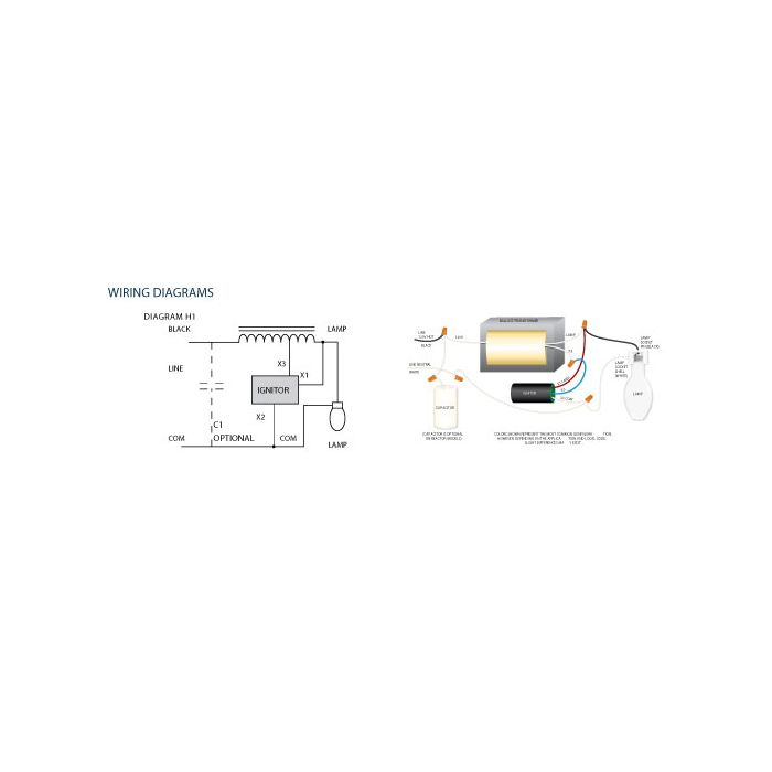
Please download these high pressure sodium ballast wiring diagram by. High pressure sodium ballast wiring diagram high pressure sodium ballast wiring diagram elegant unusual 400w hps ballast wiring diagram simple wiring.
240 Volt Ballast Wiring Diagram 240 Volt 3 Wire Split Phase
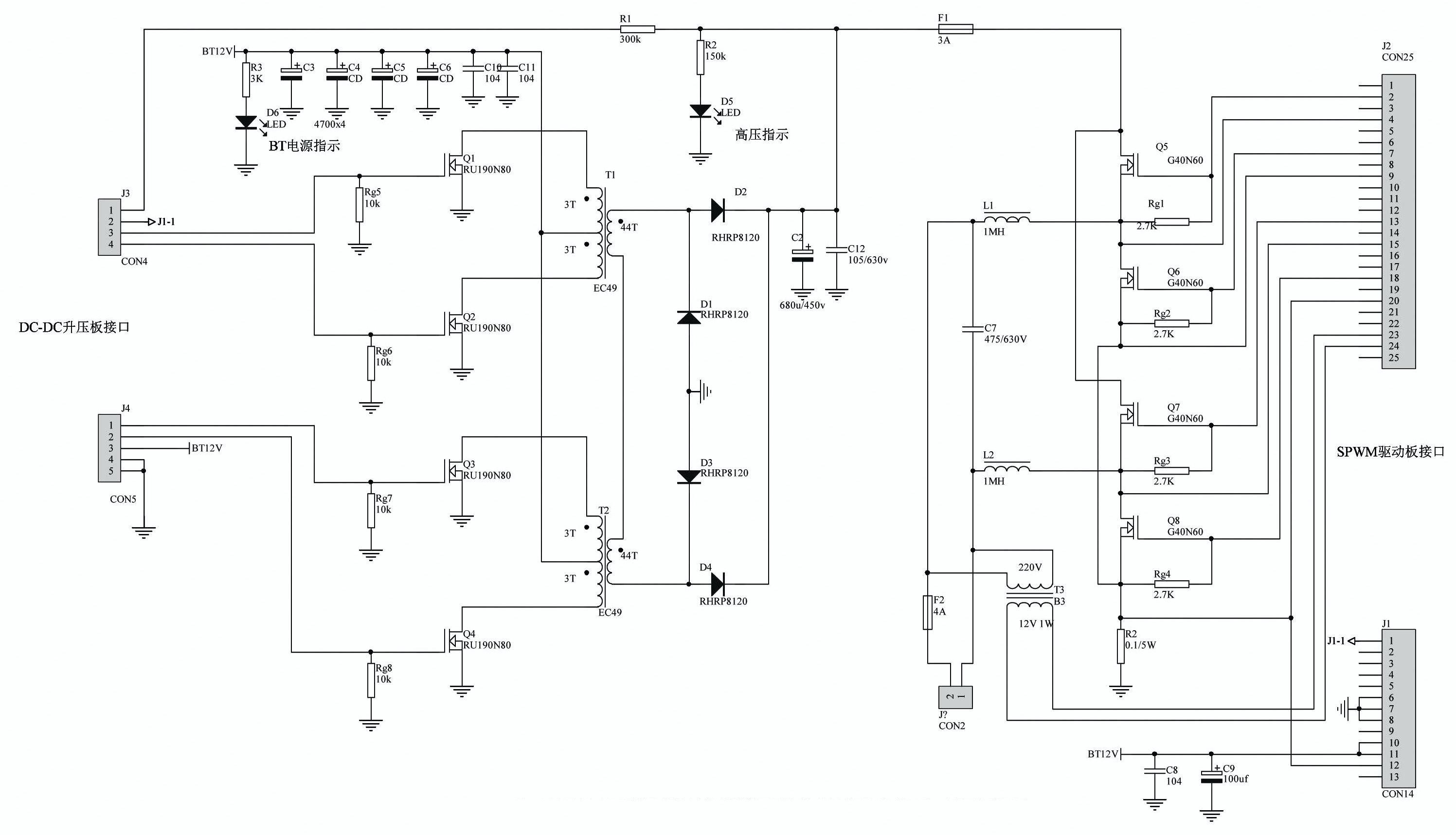
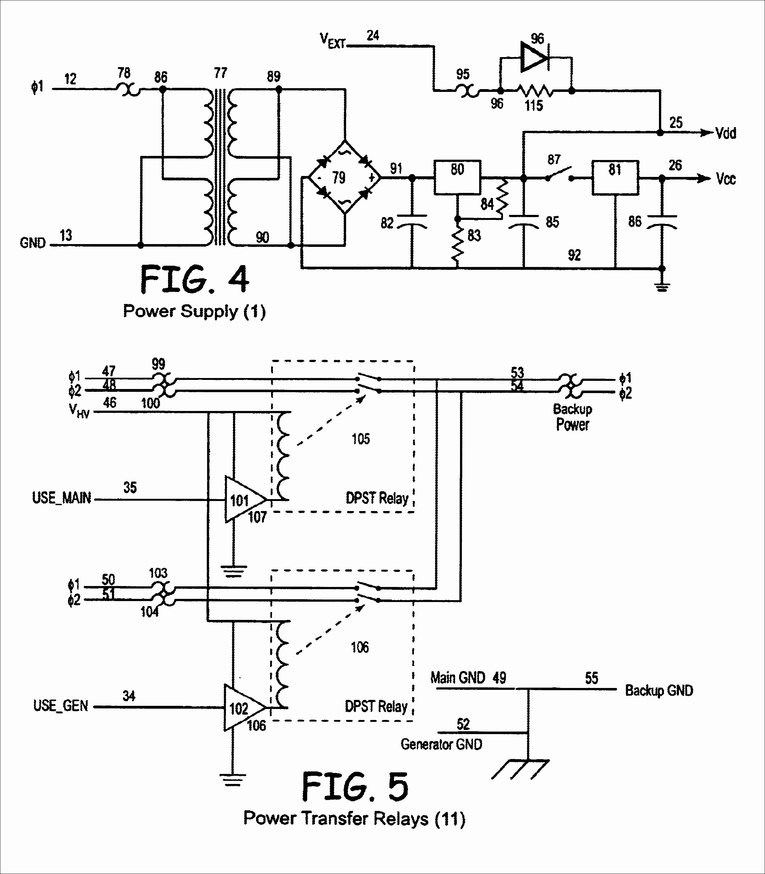
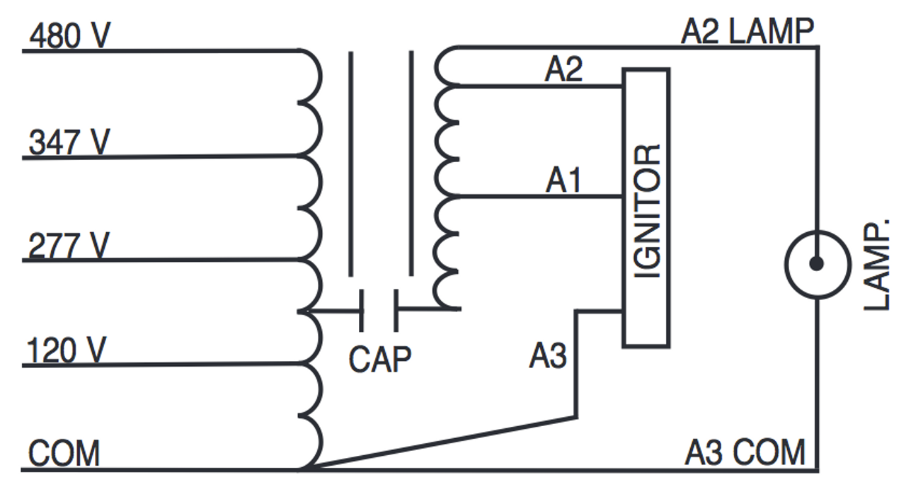
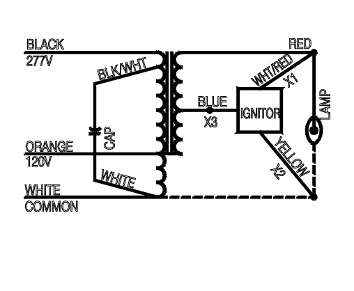
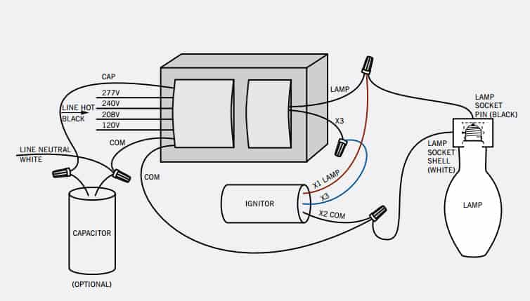
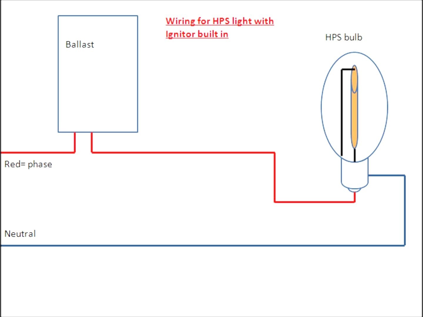
High pressure sodium ballast wiring diagram. A wiring diagram is a simplified standard photographic depiction of an electric circuit. Most magnetic hid ballasts are multi tap meaning they can be connected to several different voltages. A very first appearance at a circuit diagram could be confusing however if you could review a subway map you can check out schematics. A ballast in series with an ac current voltage source supplies the lamp with a near constant stream of current. High pressure sodium ballast wiring diagram. Getting from point a to direct b.
Here we display wiring diagrams for metal halide probe start metal halide pulse start and. It shows the components of the circuit as simplified shapes and the capacity and signal connections surrounded by the devices. High pressure sodium ballast wiring ballast wiring diagrams for hid ballast kits including metal halide and high pressure sodium ballast wiring. The objective is the very same. It reveals the parts of the circuit as streamlined forms and the power and signal links between the gadgets. High pressure sodium lamp wiring diagram wiring diagram is a simplified gratifying pictorial representation of an electrical circuit.
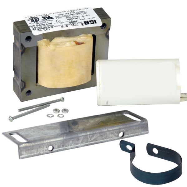
High pressure sodium ballast lamps use high pressures of sodium in an excited state to generate light. Wellborn collection of high pressure sodium ballast wiring diagram. February 2 2019 by larry a. High pressure sodium ballast wiring diagram a beginner s overview of circuit diagrams. Literally a circuit is the path that enables electricity to circulation.
