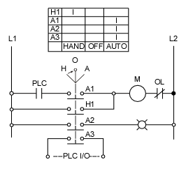
The open terminals marked by an open circle and arrows represent connections made by the user. In this lesson well examine a common industrial application of 2 wire control circuits known as a hand off auto circuit.

Selector Switches And Contacts In A Diagram What They Do
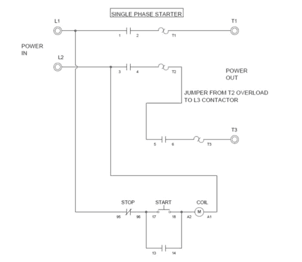
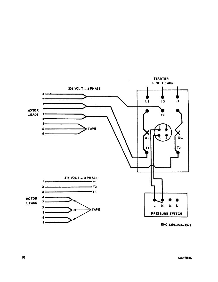
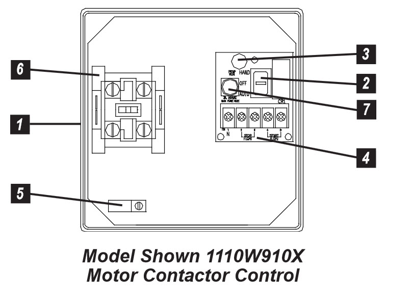
Hoa wiring diagram. Instead properly understanding location of control and mode of control can solve the issue. Wiring diagrams sometimes called main or construc tion diagrams show the actual connection points for the wires to the components and terminals of the controller. Hand off auto hoa controls are a very common and versatile control circuit which allows both automatic and manual operation. The switch is shown as a single pole. To be controlled by some automatic operation such as a sensor or plc plus allows you to easily turn the load on manually or off manually. Figure 1 is a typical wiring diagram for a three phase mag.
Multiple uses of the hoa designation for the same device is a recipe for confusion both switches are labeled with the same function which makes it unclear exactly how the motor is going to be started. A wiring diagram shows as closely as possible the actual location of all component parts of the device. Presently there is a 30 hp motor hoa wiring help. They can be used as a guide when wiring the controller. It allows loads such as motors solenoid valves electric cylinders etc. Electrical designer needing help with a wiring diagram for the following.
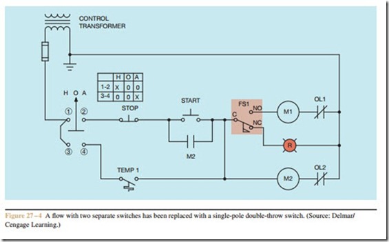
Hand off automatic controls are used to permit an operator to select between automatic or manual operation of a motor. Well discuss the devices that make up a hand off auto circuit and how. Hand off automatic controls recognize hand off automatic switches on a schematic diagram. 75hp motor 150a hmcp breaker an engineer speced out the mcc bucket. They show the relative location of the components. The circuit shown in figure 271 permits a motor to be operated by a float switch or to be run manually.
