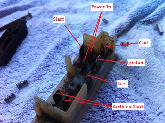
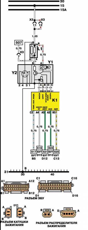
If anyone could share a wiring diagram or an easy explanation that would be sweet. Hj 1974 to 1976 schematics.

Mysandman Forums
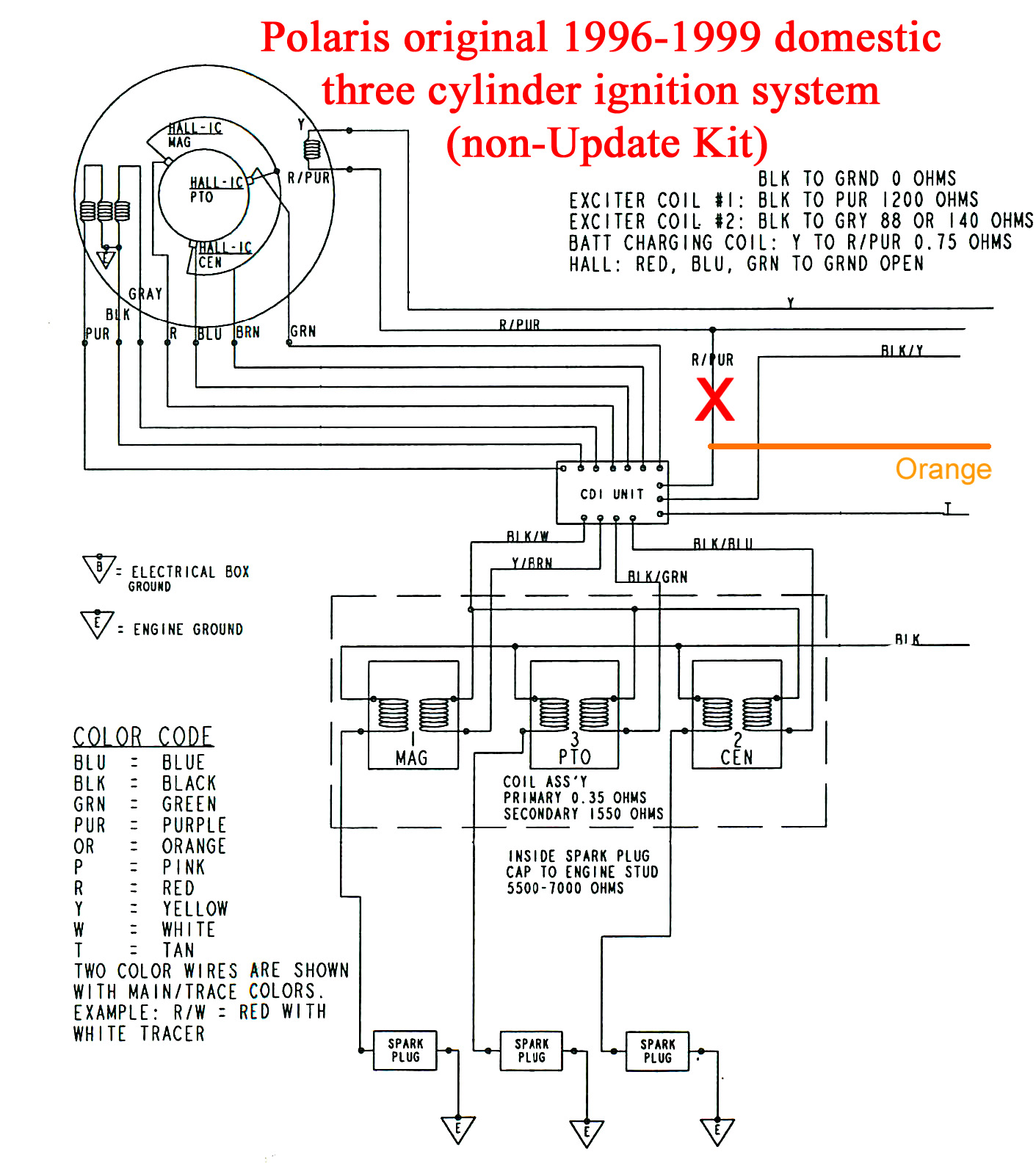
Hz ignition wiring diagram. Schematics wiring diagrams hq 1971 to 1974 schematics. Wb 1980 to 1984 schematics. Variety of boat ignition switch wiring diagram. Hz 1977 to 1979 schematics. Hx 1976 to 1977 schematics. Mouse over a model to link to the appropriate wiring schematics.
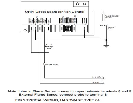
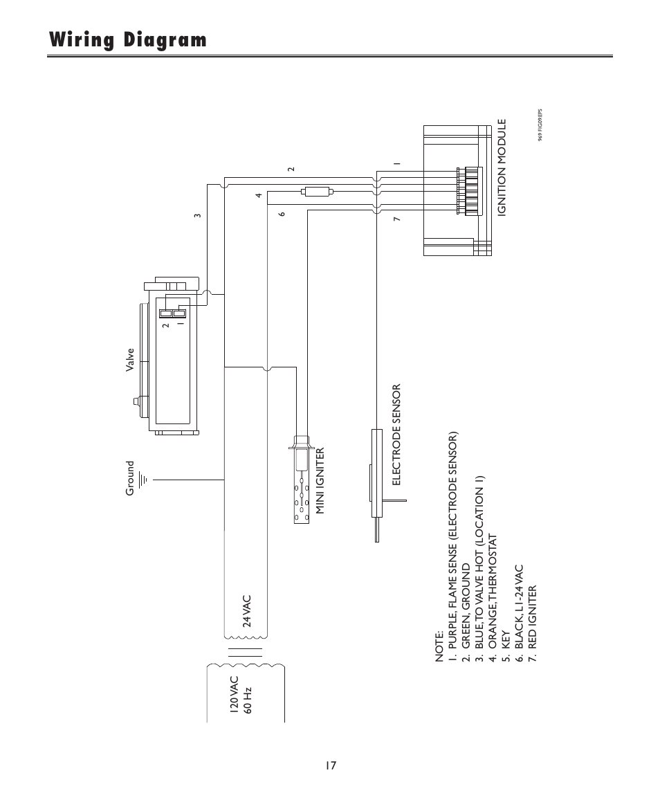
Ignition coil distributor wiring diagram size. I am using the pink wire at the 5 pin plug in the centre of the firewall. Hq schematics wiring diagrams instrument cluster wiring. If not the arrangement will not function as it ought to be. Each component ought to be placed and linked to different parts in particular manner. A wiring diagram is a streamlined traditional pictorial representation of an electric circuit.
800 x 600 px source. It reveals the parts of the circuit as simplified shapes and also the power as well as signal connections between the devices. Pertronix ignitor wiring diagram pertronix ignition wiring diagram pertronix ignitor ii wiring diagram pertronix ignitor iii wiring diagram every electrical arrangement is made up of various different components. Every time i go to crank it kills the power to the relay but disconnect it from the relay and it stays lit up on crank. I am running the ignition wire to a relay to power module. Wiring diagrams units with dual scroll compressors usage table diagram index unit production start date unit serial number 48tj016024 60 hz and 50tj016024 60 hz 111698 4798f and later 48tj020028 60 hz and 50tj020028 60 hz 12798 5098f and later 50tj016 50 hz units with 3 outdoor fans 024 50 hz 11899 0499f and later.
