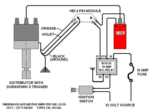
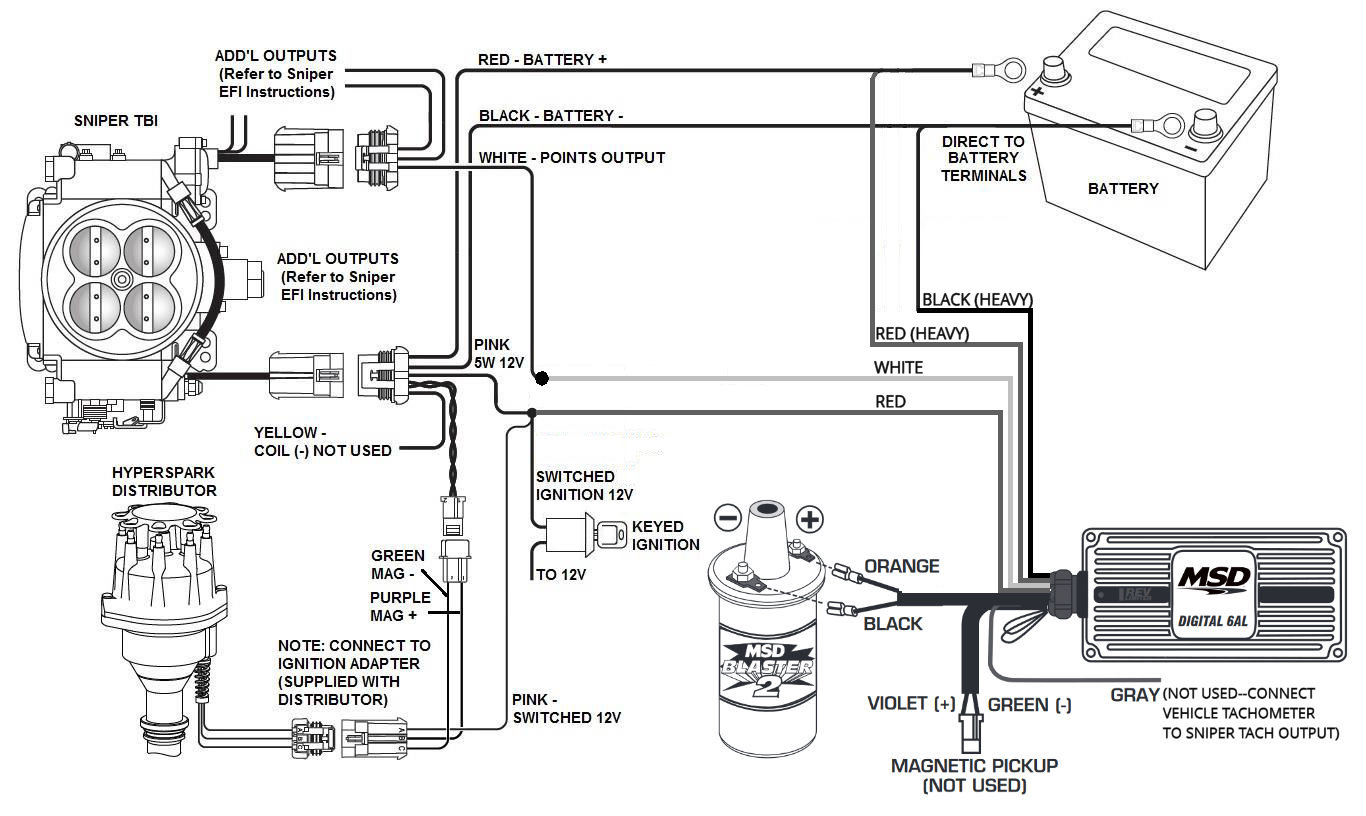
Ice billet 6061 t6 alloy distributor in small or large cap with either spheroidal graphite cast iron silicon bronze or hardened steel gear. The diagram shows booster red connecting to ignition switch i pulled my cowl off and found about 4 wires going to the ignition switch does anyone know which one to connect to im guessing it wont be the red as it is prob direct positive wire.
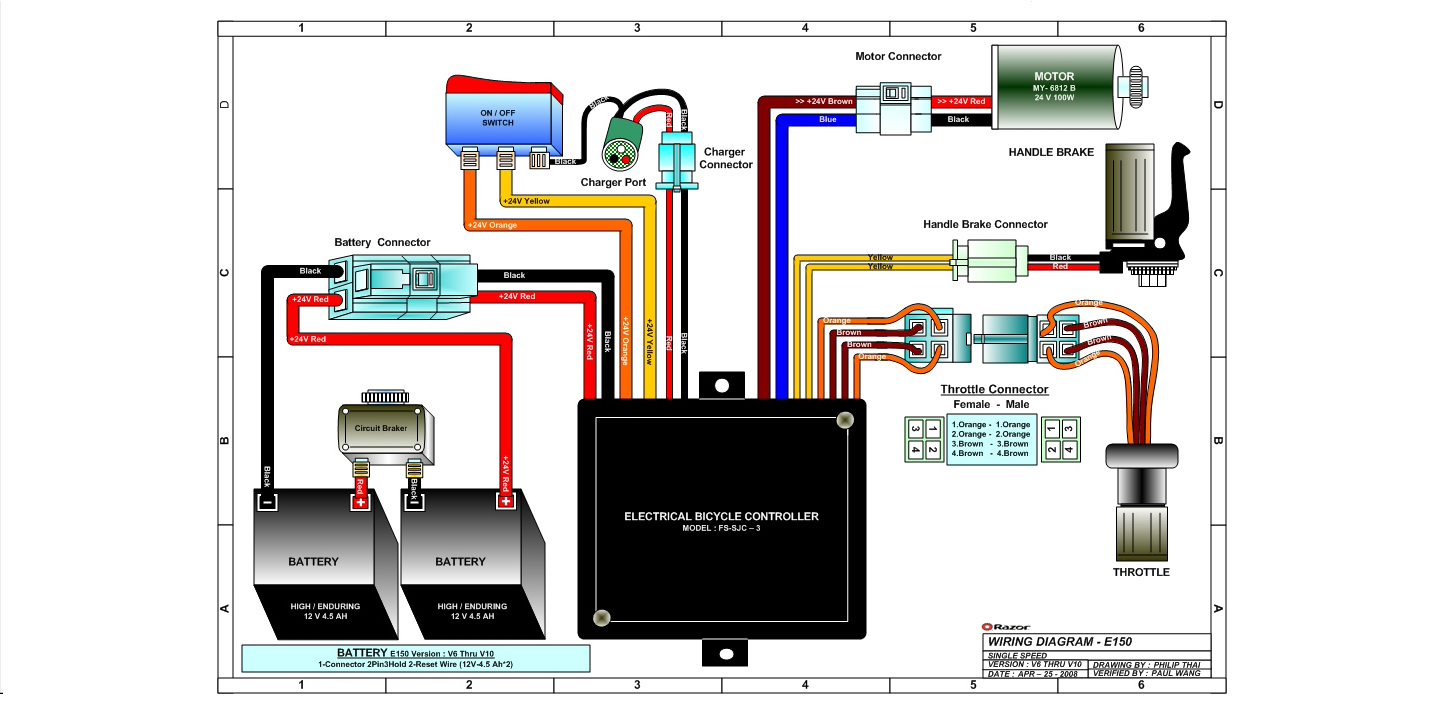
B7da69 Ice Bear Atv Wiring Diagram Wiring Library
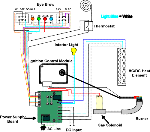
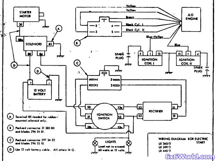
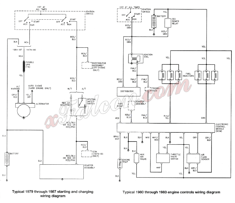
Ice ignition wiring diagram. Ice ignition control modules are not waterproof. 35 awesome ford starter relay wiring diagram a run relay is used in the automotive industry to restrict and bend the flow of electricity to various electrical parts inside the automobile. That the ice ignition will also work. Collection of frigidaire ice maker wiring diagram. A wiring diagram is a streamlined traditional photographic depiction of an electrical circuit. They allow a little circuit to govern a future flow circuit using an electromagnet to govern the flow of electricity inside the circuit.
Wiring diagram 7 amp 2 step 7842mc ignition box no booster 7842mc red white orange green 7 amp 2 step distributor coil battery wire color legend orange wire green wire. If you dont have a wiring diagram of your ignition switch handy the above chart outlines how to use your dmm to determine which wire is which on the back of the switch. 7 amp digital ignition box with 16 preloaded push button ignition curves built in map sensor vacuum input signal led indiactor and dedicated tach output. It shows the elements of the circuit as streamlined shapes and the power and also signal links in between the tools. Ice provide long wiring harnesses to allow the electronics to be mounted in a protected area inside the vehicle cabin such as under the dash or in the glove compartment. Think of the wiring harness as the vehicles central nervous system.
You will void your warranty and quite possibly have to buy replacement parts. The ice 7016 2 7 amp plus ignition control is suitable for 4 6 and 8 cyl engines and features intelligent type variable dwell spark control. Suitable for both 6cyl and 8cyl applications. Compatible with both positive leading edge or negative falling edge square wave signals from aftermarket ecus it also incorporates a built in 16 volt booster. Make sure the ignition module modules are located away from any contact with water dirt or dust. 7642mc 7 amp 2 step street race wiring diagram 7642nr 7 amp 2 step street race nitrous control wiring diagram 7840mv 7 amp street series wiring diagram 7842br 7 amp 2 step street race boost control wiring diagram 7842mc 7 amp 2 step street race wiring diagram 7842nr 7 amp 2 step street race nitrous control wiring diagram ice plug wire fitting tips.
