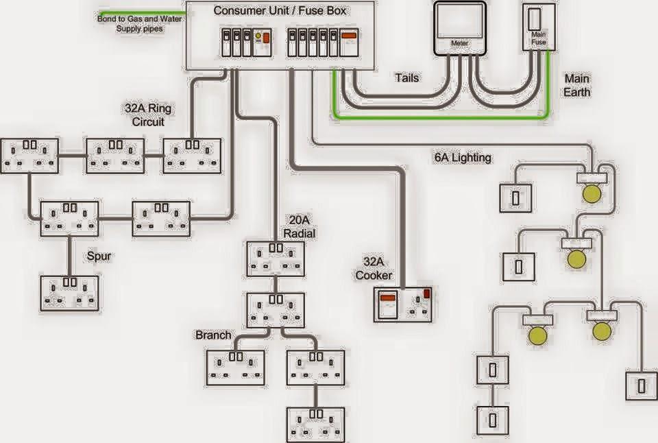
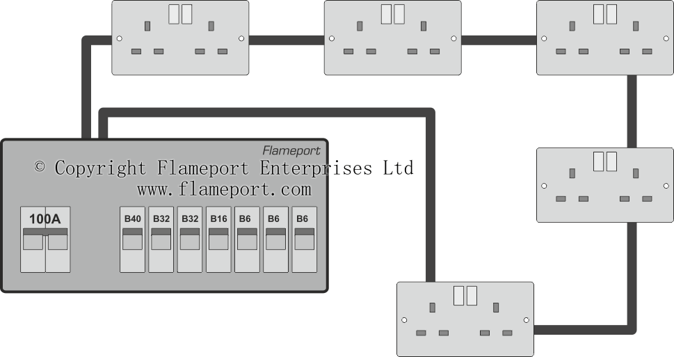
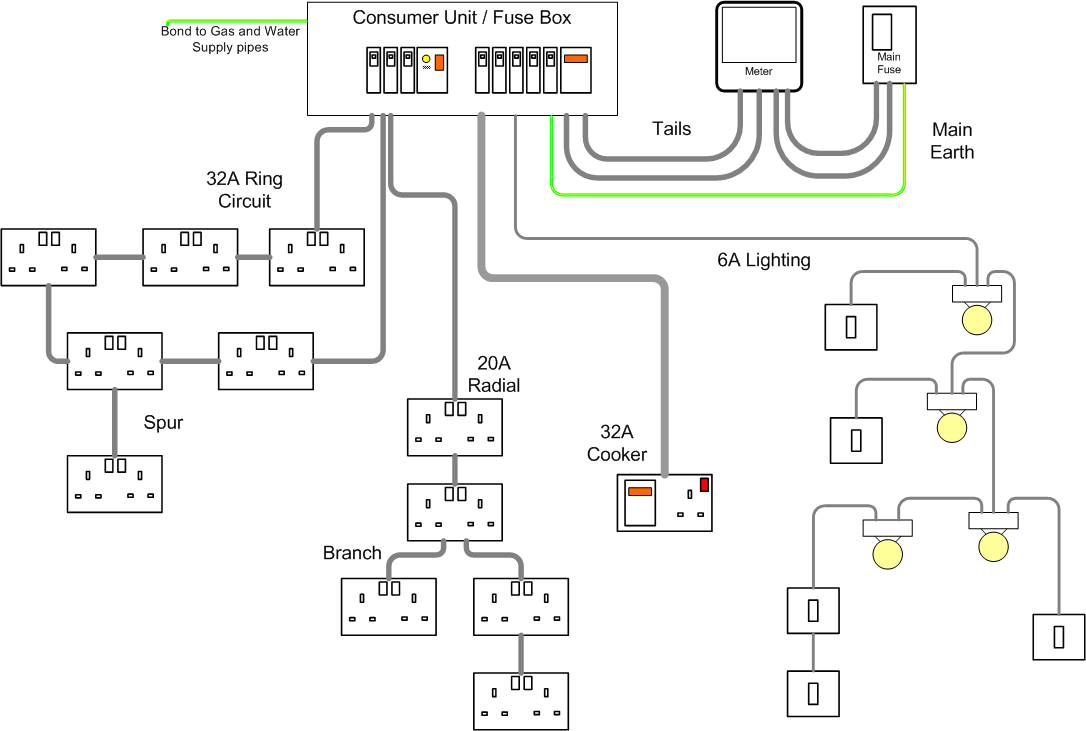
Multiple light wiring diagram. It includes advice on electrical spur wiring with diagrams so that you can find out how to wire up a spur plug socket or have a spur fitted.
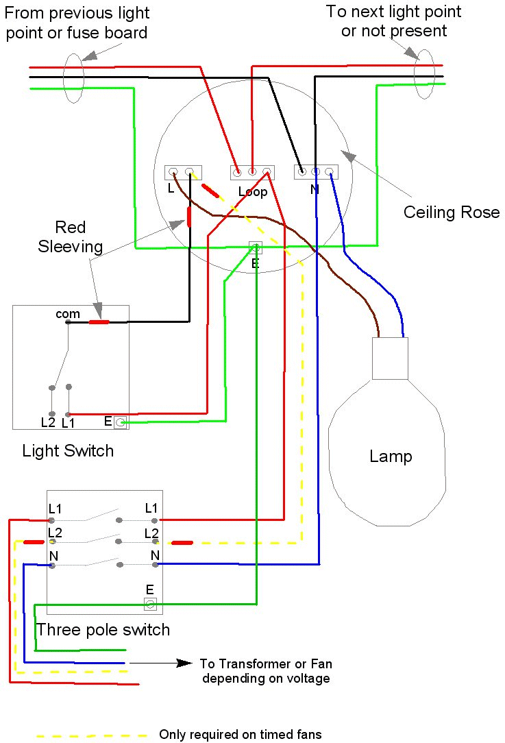
D016f Bathroom Exhaust Fan And Light Switch Wiring Diagram
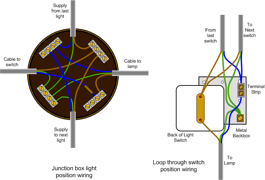
Lighting spur wiring diagram. This is an alternative way of wiring a lighting circuit. Connect the new socket or switch as shown in the appropriate wiring diagram in these fitting instructions taking care that only the copper. Wiring diagrams a surface ceiling light will be shown by one symbol a recessed ceiling light will have a different symbol and a surface fluorescent light will have another symbol. Spur socket wiring how to add an electrical socket to a circuit. The hot and neutral terminals on each fixture are spliced with a pigtail to the circuit wires which then continue on to the next light. This project is about how to add a spur socket or additional sockets to an existing circuit.
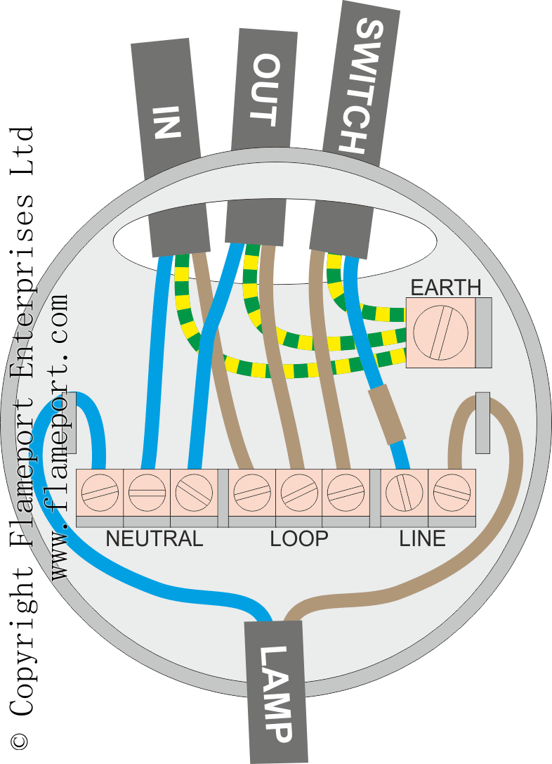
Radial circuits are used for lightingthere is one lighting circuit on each lighting mcblighting circuits are usually on a 6a mcb or 5a fuse though 10a can be used with some extra restrictions now removed in the 17th edition of the wiring regs for large circuitshowever if the area served is large more 5a or 6a circuits would in most cases be preferable. Each type of switch will have a different symbol and so will the various outlets. Feed the spur cable into the junction box. Prepare the cable route for the spur from the junction box to the new lighting point using 1mm 2 two core and earth spur cable. Wiring wall lights to ceiling lights the spur cable live brown connects to the live terminal block. The reason why the wiring of a lighting circuit is more complex than a power circuit is that each outlet or light fitting needs to be controlled by a separate switch.
Unscrew the ceiling rose or lighting circuit junction box and connect the spur cable to the loop circuit cable as shown in the diagram below. This diagram illustrates wiring for one switch to control 2 or more lights. Need to add a socket. Connect the cables as in the diagram ensuring that the load cable is connected to the appliance in use. One way of providing for this is to install a four terminal junction box in which the cable from a light and the cable from its switch can be connected to the circuit cable. The neutrals are connected together using a terminal connector.
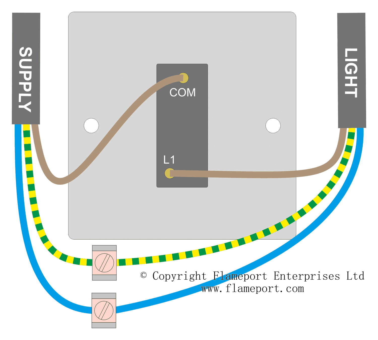
Prepare both ends of the cable and the cores. The source is at sw1 and 2 wire cable runs from there to the fixtures. Instead of taking the feed wire from the consumer unit to the ceiling rose it is taken to the switch. You will even find symbols showing the location of smoke detectors your doorbell. Unscrew the junction box cover. How to install a fused spur.
The permanent live wire is wired into the switch and the switched live into the switched live terminal. Make a diagram of where all the cores connect. If in any doubt on how to proceed.
