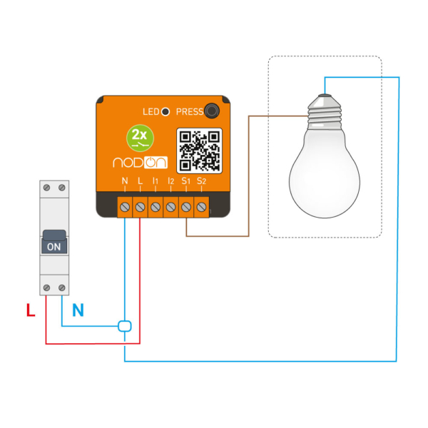
How to wire lighting circuit using impulse relay four ways switch lighting circuit. Click image to enlarge.

Bistable Relay Tester
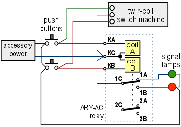
Impulse relay wiring diagram. Herein you will also see the table of the cable color codes. Inside the lighting impulse wiring diagram we will see parts like. It must be connected in parallel to the coil of the relay see diagram. A video tutorial on how to perform control wiring of reverse forward in 2 different diagram. 5 26 seies 26 series. Particularity of this circuit is that it can be used in a centralized system for home automation.
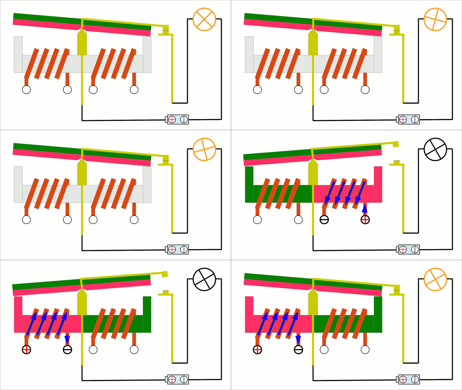
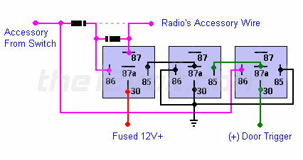
The first press to the button turns the relay on and the second press turns it off and relay in the circuit operating room illuminates. Similar to the momentary to constant configuration we can engage and disengage the latched output with a single pulse from a switch or an output from an alarm or remote keyless entry. The first pulse from the switch will engage the latch. Brake switch ignition switch resistor horn rectifier electric choke battery starter relay starter motor ignition coil cdi unit stator safety tether switch and headlight. Latched onoff output using a single momentary negative pulse positive output relay wiring diagram. Example of wiring diagram of type 02600 this module is necessary when using between 1 and a maximum of 15 illuminated push buttons in the coil circuit each 1 ma max 230 v ac.
Sealed construction 75 cm insulated flexible wire termination. Electronic relays and program timers impulse memory relay 68 wiring diagram examples dimensions diagram 175 60 45 90 55 44 ir116k a1 a2 onoff 12 14 on off ir116k 12 onoff a2 off on a1 14 l n local control of impulse relays ir116k a2 a1 12 14 onoff off on ir116k a2 a1 12 14 onoff off on local control each relay is locally controlled by push buttons at the load r z. A digital impulse relay is a electronic circuit that mimics perfect the all functions of a impulse relay with ratchet mechanism.
