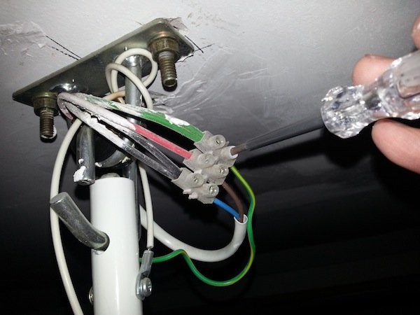
Ceiling fan wiring diagram. With these diagrams below it will take the guess work out.

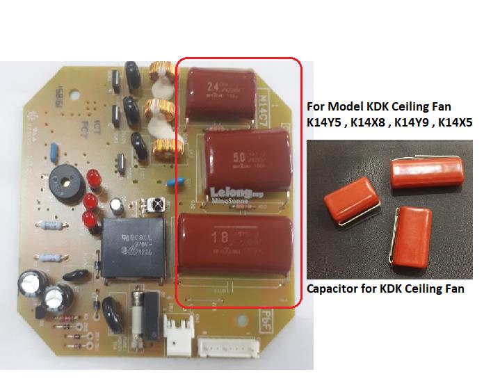
Ceiling Fan Speed Problem Solved How To Repalce The Capacitor
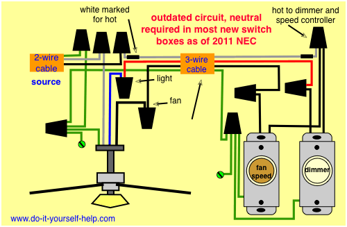
Kdk fan wiring diagram. View and download kdk 20rgf service manual online. After wiring check the rotation direction for k55dtl and k55utl which do not have two speed motor. From the switches 3 wire cable runs to the ceiling outlet box. M40r operating instructions specifications remove the set screw and mounting plate from stand before installing the fan. High quality ceiling fan wiring diagram capacitor. The product has good stability impact resistance current overload and strong low loss hig.
K15v0 k15w0 s k15w0 sl k15w0 k12v0 k12w0. 30rgf 25rlf 30rle 25rgf 20rlf. Wiring diagram wiring diagram yellow p white brown cord regulator brown white red i capacitor thermal fuse brown black source blue n brown j terminalj. Abs or polypropylene shell 2. Part name qty remarks 1 h40bk0920bma guard mark ass 1 m0028 2 400ss0901ama front guard coat 1 sm004 3 401uh0807zmd spinner 1 bz344. White and black lines to the r s and t terminals.
20rgf fan pdf manual download. Location of parts m40rs 3. Pick the diagram that is most like the scenario you are in and see if you can wire up your fan. Made of silicon electrical steel sheets and winded with 9999 pure enameled copper wire fan stator is the core technology in manufacturing electric fans. Ceiling fan wiring diagram capacitor1. This might seem intimidating but it does not have to be.
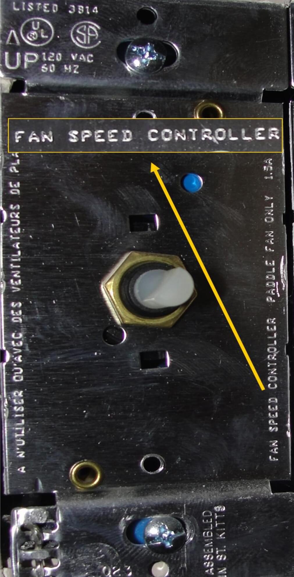
Brown blue electric fan orbital fan model no. This wiring diagram illustrates the connections for a ceiling fan and light with two switches a speed controller for the fan and a dimmer for the lights. Take a closer look at a ceiling fan wiring diagram. Wiring diagram wiring diagram three phase k40dtl k40dth k45dtt k45dtl k45dth k55dth k40utl k40uth k45utt k45utl k45uth k55uth reo motor printed in thailand. Safety parts part no. The source is at the switches and the input of each is spliced to the black source wire with a wire nut.
3ø wiring diagrams 1ø wiring diagrams diagram er9 m 3 1 5 9 3 7 11 low speed high speed u1 v1 w1 w2 u2 v2 tk tk thermal overloads two speed stardelta motor switch m 3 0 10v 20v 415v ac 4 20ma outp uts diagram ic2 m 1 240v ac 0 10v outp ut diagram ic3 m 1 0 10v 4 20ma 240v ac outp uts these diagrams are current at the time of publication. Replacement parts list m40rs packing list 4 ref no. K11z1 part 1 part 2. Ceiling fan installation manual. Electric fan order number.


