A wiring diagram is a streamlined standard photographic depiction of an electrical circuit. The total motor current flows into terminal 1.

10971820 Klixon Switch Reset Button
Klixon thermal switch wiring diagram. The voltage change switch cleverly alters the power connections from the klixon and the two main windings upper and lower. 2 the klixon in the gwi circuit from gregs wiring diagram. Thermal switches can be retrofitted on the coil end but the result is an increased reaction time. In single phase motors one single thermal switch is used. The klixon disc is the neutral point of the motor. The 7851 and 7854 series.
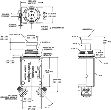
Each heater is in series with one of the phase windings of the motor as well as with one of the contacts on the. Klixon three phase phenolics motor protector consists of a molded phenolic base assembly containing three heaters and a klixon snap acting thermal disc with three contacts. The 7851 and 7854 series closed construction circuit breakers are weatherproof sealed for protection against moisture dust grease fuel vapors and other harsh environments. The three klixon terminals are used to handle motor protection properly in 115v and 230v operations. F3ah a078 iav 001 wiring diagram moreover emerson thermostat wiring diagram for home besides klixon motor. Lot of 300 new klixon 6ap00632 motor thermal cutoff.
Jan 29 2 the klixon in the gwi circuit from gregs wiring diagram. See mini cas manual wiring diagram technical data. In that way all three phases are in contact with a thermal switch. The three klixon terminals are used to handle motor protection properly in v and v operations. In three phase motors 2 thermal switches connected in series are placed between the phases of the motor. The klixon 7851 and 7854 series thermal breakers were designed to protect wiring and meet the harshest environmental requirements.
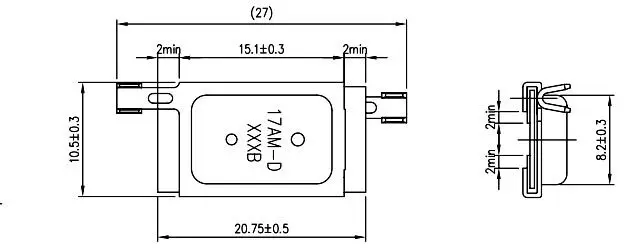
Temperature sensor componentsheraeus introductionheraeus heraeus sensor element series h platinum resistance high temperature range 70 c to. Mini cas supervision relay the thermal switches are wired in series with the leakage sensor. 1nt 2ace 2am 2bm 2mm 2tc 3am 3bt 3cr 3hm 3mp 3nt 3p 3sb 3sp 3tc 4am 4ba 4bt 4cr 4sp 4tm 5bt 5sp 5tc 5tm 6ap 6ps 6tc 7am 7bt 7ht 8am 8ea 8ht 8sp 9ht 9tc 10ht 12ht 14ht 15aa 15am 15hm 15tc 16hm 17am 20tc 30aa 31aa 32aa 31hm 32hm 33hm 34hm 35hm 37hm 40aa 41aa 42aa 1822 4344 4391 6752 6766 6790 7235 7236 7270 7271 7274 7277 7851. A klixon is an overload protector used mostly in fractional horsepower if i have it i will get the schematic for you. Collection of klixon motor protector wiring diagram. It shows the components of the circuit as streamlined shapes and the power as well as signal connections between the tools.
The total motor current flows into terminal 1.
