Presented by king of the house home inspection duration. If not the structure wont function as it should be.
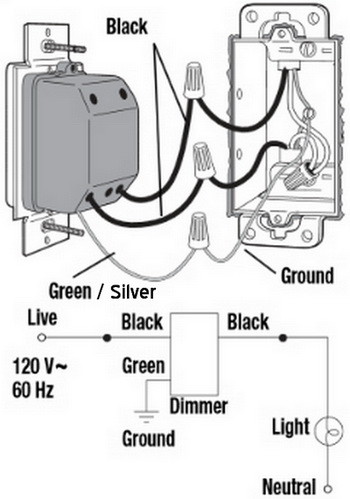
New Dimmer Switch Has Aluminum Ground Can I Attach To
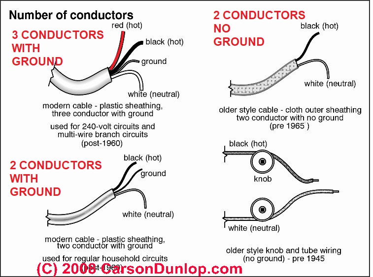
Knob and tube light switch wiring diagram. The source is at sw1 and 2 wire cable runs from there to the fixtures. Knob and tube wiring is one of the original forms of electrical wiring in homes popular from the late 1880s until the 1930s when it fell out of favor. Knob and tube wiring diagram youll need a comprehensive professional and easy to comprehend wiring diagram. Help with a knob and tube electrical wiring project. Find your knob and tube wiring diagram here for knob and tube wiring diagram and you can print out. The hot and neutral terminals on each fixture are spliced with a pigtail to the circuit wires which then continue on to the next light.
How to wire a single pole light switch duration. Knob and tube wiring and adding a switch electrical question. With this sort of an illustrative guidebook you are going to be able to troubleshoot prevent and total your tasks with ease. How can i replace knob and tube wiring in the basement and adding switches. This article answers basic questions about knob and tube electrical wiring. Here i think but am not certain it appears as if the knob tube comes into a box around an old gas line see photo but i may be mistaken.
Knob and tube wiring. The older parts of the house have knob tube wiring and there is evidence of gas plumbing for lighting before the knob tube was installed. The instructions say to attach. Each part ought to be placed and linked to different parts in specific manner. When replacing knob and tube wiring in the basement area with grounded circuits the electrician forgot to use 3 way. Search for knob and tube wiring diagram here and subscribe to this site knob and tube wiring diagram read more.
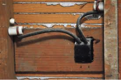
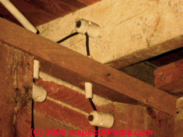
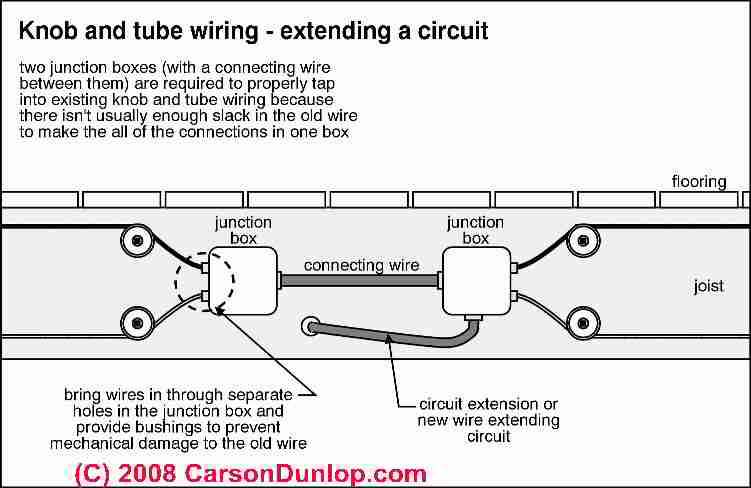
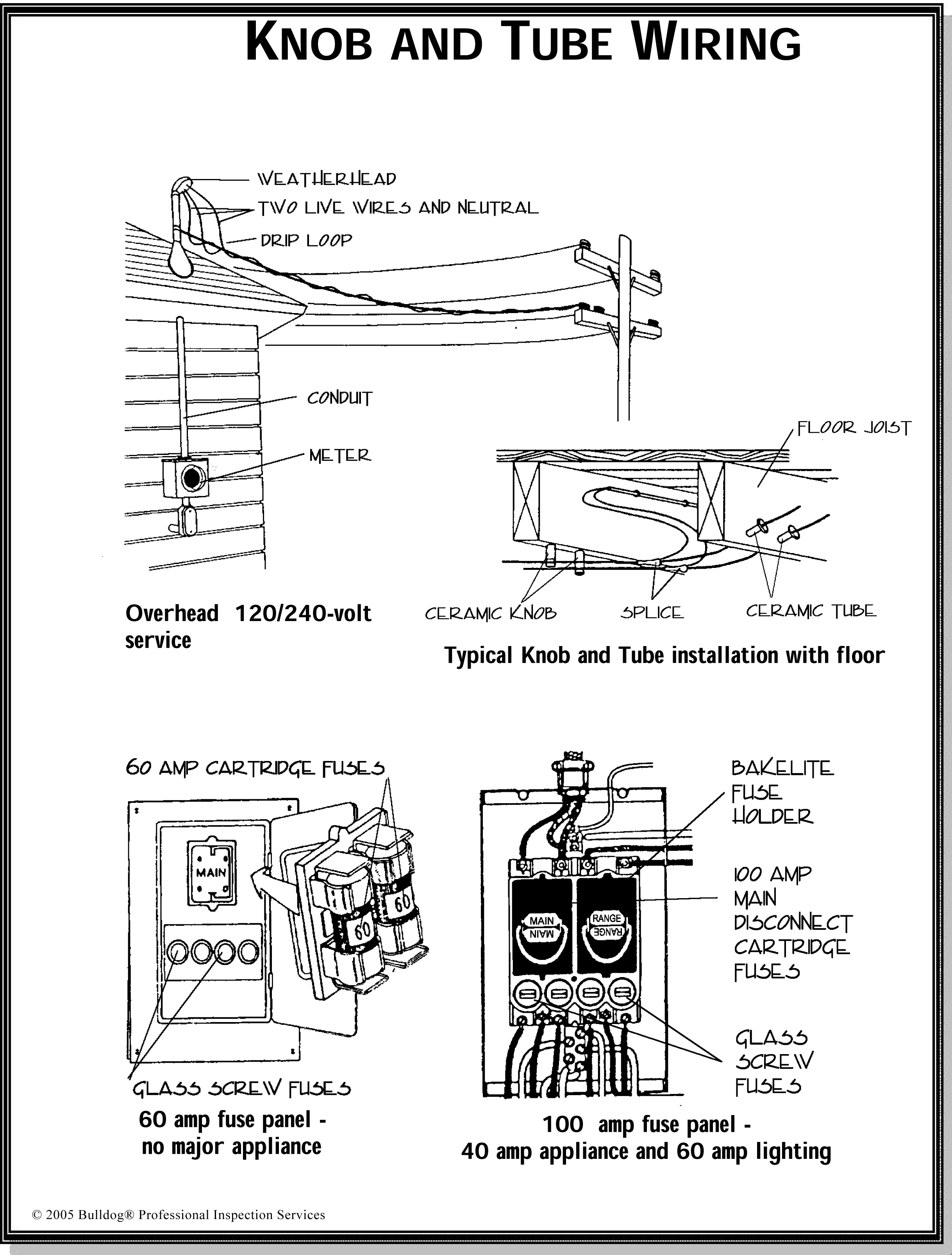
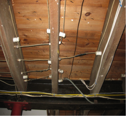
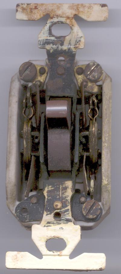
Guide to knob and tube electrical wiring. This diagram illustrates wiring for one switch to control 2 or more lights. Knob and tube wiring sometimes abbreviated kt is an early standardized method of electrical wiring in buildings in common use in north america from about 1880 to the 1930s. At the time it was the standard for wiring new electrical installations due to its relatively low cost compared to the other options of the time like armored cable and conduits which could. It consisted of single insulated copper conductors run within wall or ceiling cavities passing through joist and stud drill holes via protective porcelain insulating tubes and supported along their length on nailed. We define knob and tube wiring we include photographs that aid in recognition of this generation of electrical wiring and we describe both proper and improper kt wiring installations repairs or circuit extensions.
Knob and tube wiring diagram knob and tube 3 way switch wiring diagram knob and tube light switch wiring diagram knob and tube switch wiring diagram every electric arrangement consists of various distinct pieces. Knob and tube 3 way switch wiring diagram knob and tube light switch wiring diagram knob and tube switch wiring diagram. Project 1 basement wiring upgrade. Multiple light wiring diagram.





/cdn.vox-cdn.com/uploads/chorus_asset/file/19585969/wiring_problems_xl_banner.jpg)


