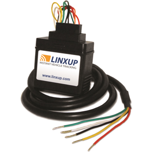
It shows the parts of the circuit as streamlined shapes and also the power as well as signal links in between the gadgets. A wiring diagram is a streamlined conventional pictorial depiction of an electrical circuit.

How To Install An Obd Plug In Linxup Gps Tracking System
Linxup gps wiring diagram. A wiring diagram is a simplified standard pictorial depiction of an electric circuit. Verify the ignition wire by measuring the operating voltage while the key is. Follow the wiring harness from the ignition switch to identify the ignition wire and constant power wire. It is a good idea to use a voltage meter to identify the wires correctly. Verify the ignition wire by measuring the operating voltage while the key is turned to the on or start position the voltage should read 0 vdc when the key is in the off position and typically between 11v and 14v when in the on position. Locate the vehicles ignition wire reference the vehicles wiring diagram in order to locate.
Verify the ignition wire by measuring the operating voltage while the key is turned to the on or start position the voltage should read 0 vdc when the key is in the o position and typically between 11v and 14v when in the on position. Locate the vehicles ignition wire reference the vehicles wiring diagram in order to locate. Connect the linxup black wire to your vehicles chassis. Collection of linxup wiring diagram. You can also search for the wiring diagram of your car make online. It reveals the elements of the circuit as simplified forms and the power and signal connections in between the devices.
Strip the black wire on the linxup gps device. The gps tracker will need to be connected with these wires. Linxup wiring diagram sample collection of linxup wiring diagram. Locate the vehicles ignition wire reference the vehicles wiring diagram in order to locate. This connection serves as a ground for the device.


