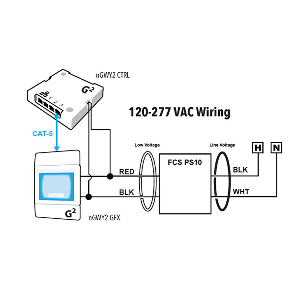
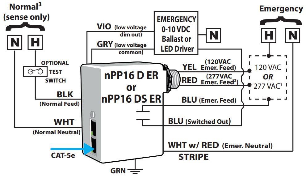
Within a typical nlight network multiple zones are wired individually to a bridge. The nlight device is typically also a power pack and can provide power to a local sensor.
Holophane Wiring Diagram
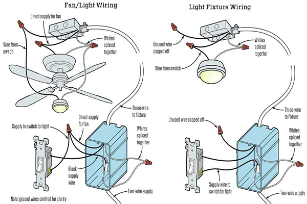
Nlight wiring diagram. Nlight is your network lighting controls system with wired or wireless options that is easy to specify install and use that grows with your business today and tomorrow. See maximum distances per wire gauge in fixture installation instructions. Consult wiring diagram a. A unique conceptual diagram. Contents 1 nlight control system overview 04 11 introduction 04 12 system architecture 05 121 nlight enabled device 05 122 nlight control zone 06 123 nlight channel 07 124 nlight operational mode 10 125 nlight backbone network 14 13 system power 16 14 system control 17 2 hardware installation 18 21 install backbone 19 22 install zones w power packs 20. Rj 45 male terminations t568b 1500 ft max cable length per zone.
40 literature. Requires a network drop similar to a network printer. With nlight you can control indoor and outdoor spaces seamlessly while reducing energy costs aiding in building code compliance improving occupant comfort and much more. Nlight control system installation worksheetnlight project installation form. So if you wish to secure all of these incredible images related to nlight lighting controls wiring diagram. In a room or area that are daisy chained wired together with cat 5 cabling.
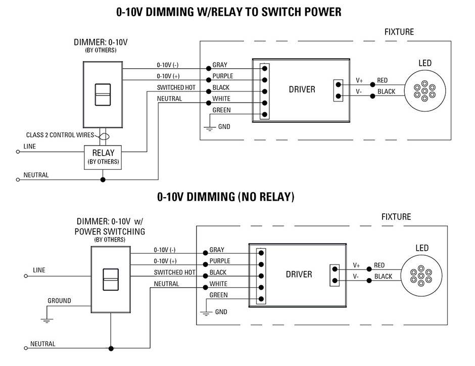
The device in an nlight network that connects the network of sensors power packs wallpods and bridges to the buildings ethernet. This section includes a set of fixture connection diagrams each with a similar format.

