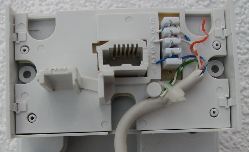
Hi this video is a very quick example of how to wire up a nte5 master socket as found in the uk on bt and virgin media telephone lines. C1 18μf capacitor r1 470kω out of service resistor r2 bell wire resistorchoke colouring says ω meter reads 77ω inside the nte5c telephone master socket 5c.

Hd 7649 Palomino Pop Up Camper Wiring Diagram Motorhomes For
Nte5 wiring diagram. For much more detail then please watch my longer 22 minute. This is how the telephone wiring colour code looks wired with the stripey telephone cable. Bt installed nte5 units have a little bt logo in the top left of the unit. 3 nov 2006 messages. The faceplate the front bottom part of the nte5 for example to connect extension wiring. You can see the test socket revealed to allow you to check the bt line before your own wiring.
The lower half of the front plate and associated wiring is the customers while the permanent wiring on the non removable section behind this remains the responsibility of the service provider. Note that the pictorial view shown above only serves to indicate the two differing types of sockets and wiring connections. The wiring diagram for a master lju socket is shown here. The nte5 tends to. Further nte5 wiring instructions are contained in this leaflet. The face plate on the nte5 connects user side wiring to the master socket by the dummy plug this goes into the test socket this is the socket used to test if your user.
If wiring from an lju type master socket then that is covered later on. Components from left to right. R1 service resistor r2 bell wire resistor c1 ring capacitor. Answer to q3 simply run a length of telephone cable from the old junction box to the new nte5 and connect the old drop wire via the new cable to the big terminals on the back of the nte5 sureitsoff 5 feb 2011 4. Lift up the red coloured connection cover and thread the 2 data cable wires in the same way as shown above for nte5c and close the red cover to make the. For installations using the nte5 line box nte for network termination equipment the demarcation point is actually within the socket.
A circuit diagram of the bt openreach nte5c telephone master socket. My guide to replacing a bt openreach master socket nte5a same for virgin talk talk etc bt master socket pre nte5 wiring diagram. Contrary to how it might seem c1 is connected to terminals 2 3 not 1 4. This is the telephone wiring colour code for the nte5 bt master socket with the cable feeding extension sockets attached to the customer removable front plate. In home data wiring 1. If no nte5 is installed the next section explains all about installing an nte5 and the user wiring.
The introduction of the nte5 meant only bts wires are fitted into the back of the socket with a test phone socket on the front and any extensions are wired into a separate removable front platesocket this can be removed should there be an issue with the extension wiring or to eliminate this from the investigation. The red connection point found on the reverse of the mk4 vdsl filter front cover is used to connect home data extension wiring.


