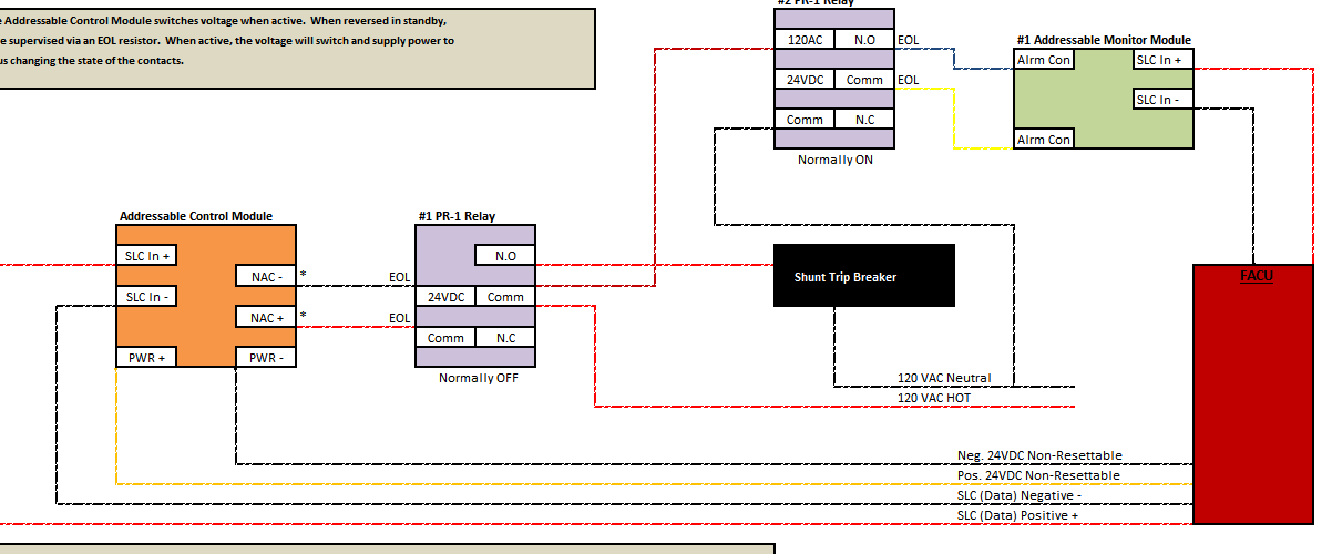
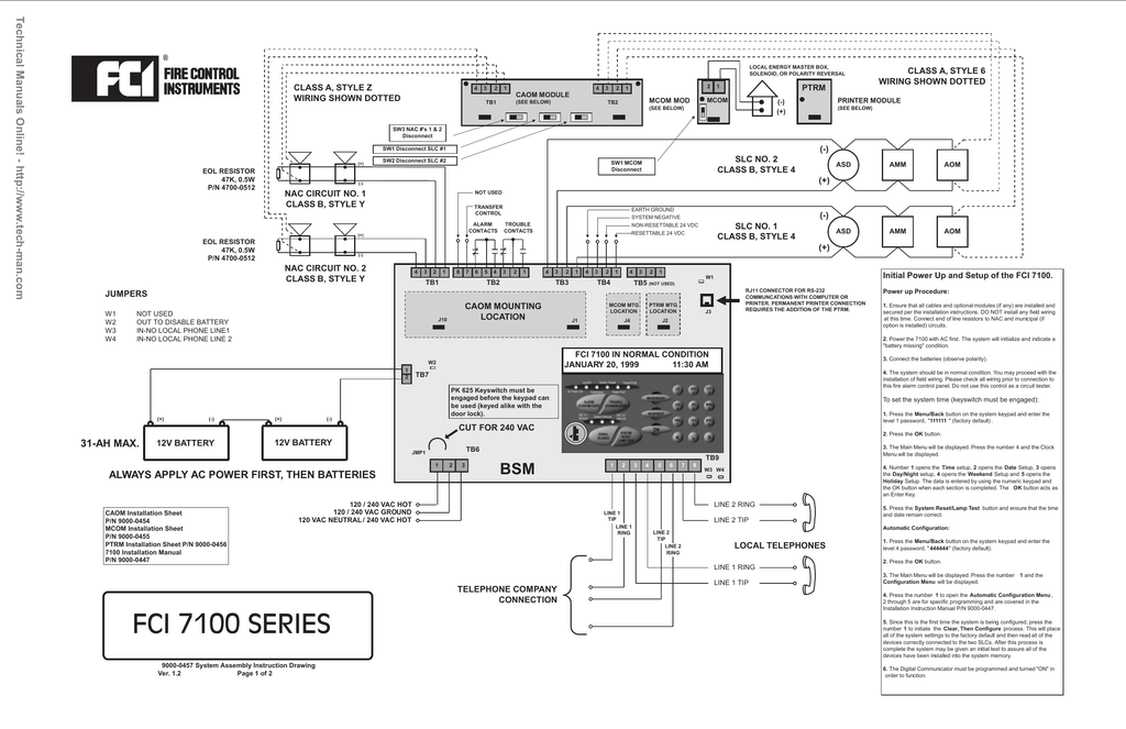
The aom 2rf is compatible with the e3 series s3 series and 7100 series fire alarm control panels. A wiring diagram is a streamlined conventional photographic depiction of an electric circuit.

Honeywell Hpff12 Operation Manual Page 53
Fci aom 2 wiring diagram. A wiring diagram is an easy visual representation of the physical connections and physical layout of the electrical system or circuit. The aom 2sf is compatible with the e3 series s3 series and 7100 series fire alarm control panels. The aom 2rf module is designed for installation in the signaling line circuit of any gamewell fci analog addressable fire alarm control panel. It shows the way the electrical wires are interconnected which enable it to also show where fixtures and components could be coupled to the system. Aom 2sf wiring diagram what is a wiring diagram. The aom 2sf is designed to mount in a 4 1016 cm square junction box 2 18 55 cm deep.
It shows the parts of the circuit as streamlined shapes and also the power and also signal links between the gadgets. Table 1 lists the relay contact ratings. The aom 2rf is designed to mount in a 4 1016 cm square junction box 2 18 553 cm deep. Gamewell fci analog addressable fire alarm control panel. Assortment of aom 2sf wiring diagram. The aom 2rf is an addressable output relay control module.
The module contains a panel controlled led. The aom 2sf allows a gamewell fci addressable fire alarm control panel to switch an external power supply such as a dc power supply or audio amplifier up to 80vrms to notification appliances. The signaling line circuits of gamewell fci analog addressable fire alarm control panels are designed to accommodate up to 159 modules per circuit. The aom 2rf allows a gamewell fci addressable fire alarm control panel to switch discrete relay contacts via software code commands.


