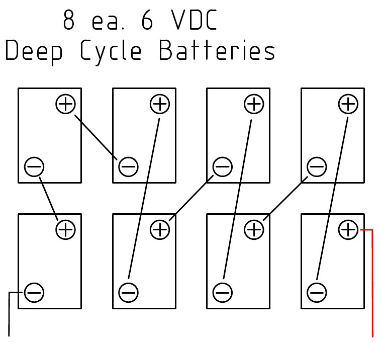
Ill try and show it in a diagramb is the battery is a series connection and are parallel connections. The side of the light unit has been marked 12v 200watt by the previous owner.
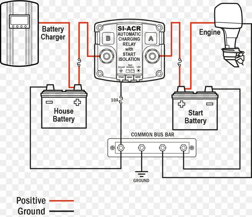
Battery Charger Wiring Diagram Battery Management System
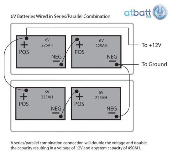
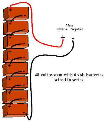
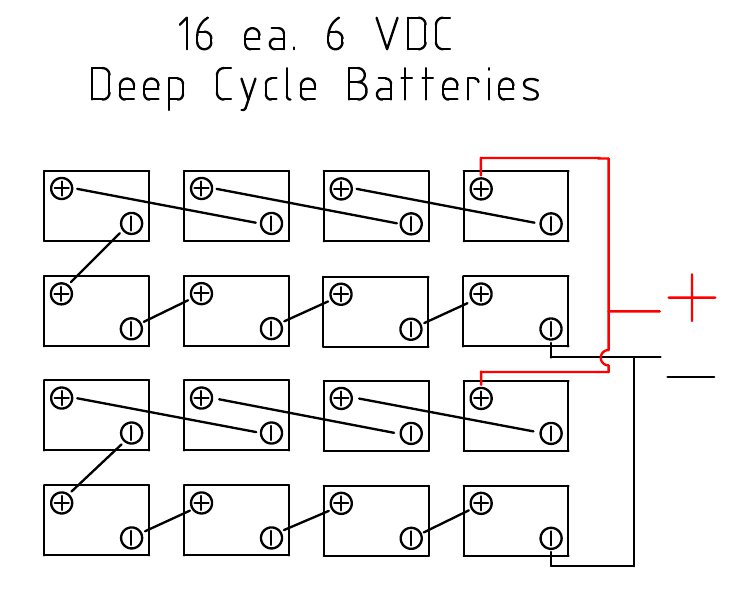
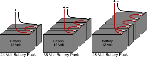
Series battery wiring diagram. The left to right series connection add the two 12 volt batteries to make 24 volts. Use series parallel wiring in combination this diagram shows a combination series and parallel circuit to increase both the battery current and voltage level at the same time. The result would be a battery bank that produces 12v and 225ah. The packs drive 4 sets of lights through out my business. The two methods of modifying a circuit are called parallel and series. A basic principle of electricity is that electrons flow through a circuit.
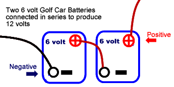
B b b b b b b b terminal 1 terminal 2 b b b b b b b b thats the most efficient method of achieving a 240v output across terminals 1 and 2. In our illustration we show two 6v batteries with 225ah wired together. First we measure the voltage from each battery. I am not sure if i should wire them in series parallel or combination. Then we wire them in series by connecting the negative lead connected to aluminum foil to the positive lead of the other battery. The wiring has been removed and i will be rewiring it.
Theyre pushed from the positive terminal of a battery through the wiring until they return to the negative terminal of the battery. In a series configuration the batteries are wired per the diagram below and the result would be a doubling of the voltage while the capacity remains the same. The unit is wired to the building correctly i just need help on the battery pack. Wiring batteries in a series. Assume this time we are using 12 volt batteries. Wiring batteries in parallel.
Wiring multiple power sources in series will increase the available voltage. In the former the electrons can.
