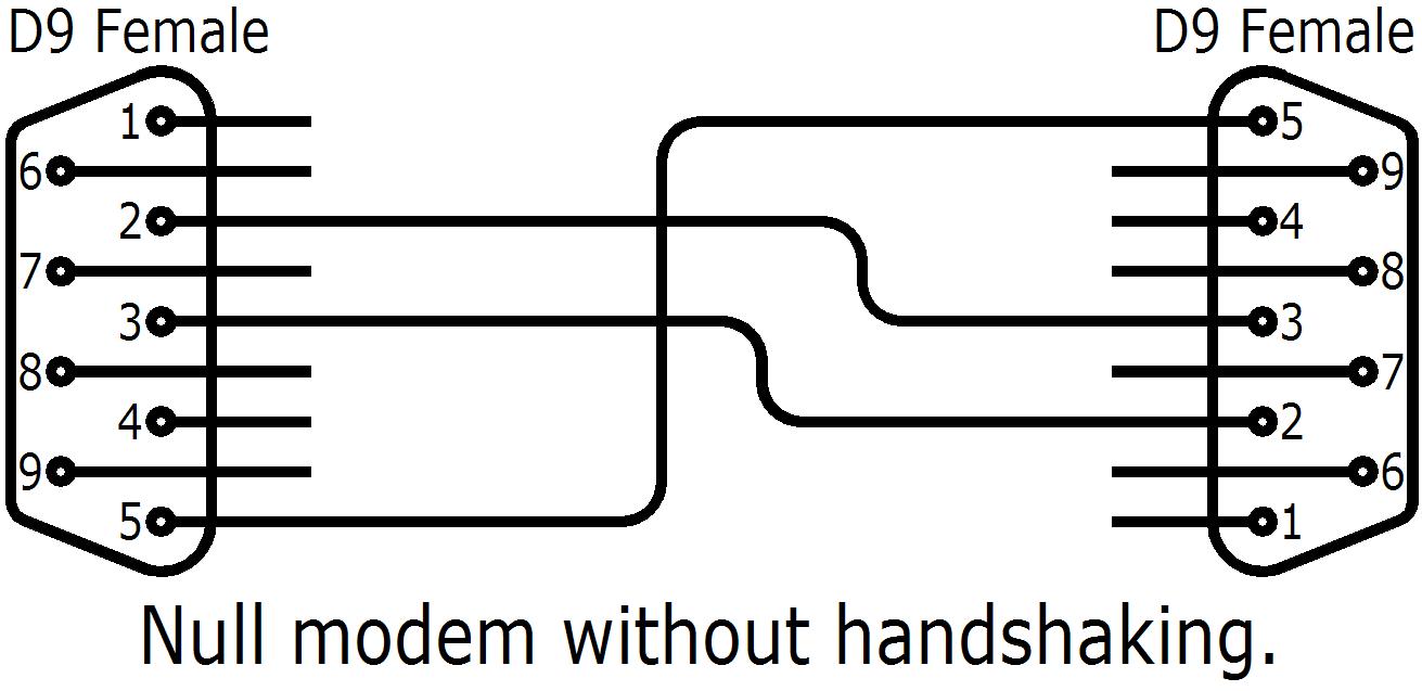
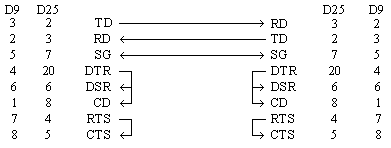
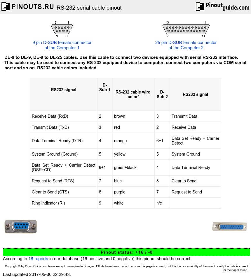
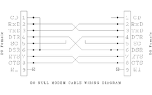
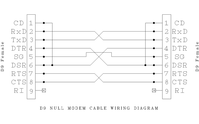
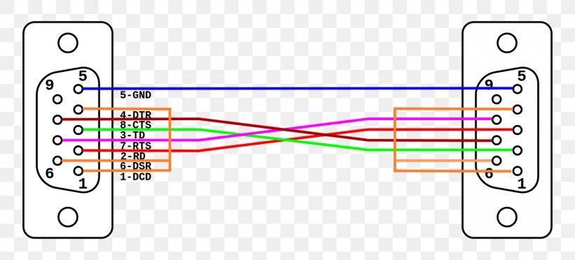
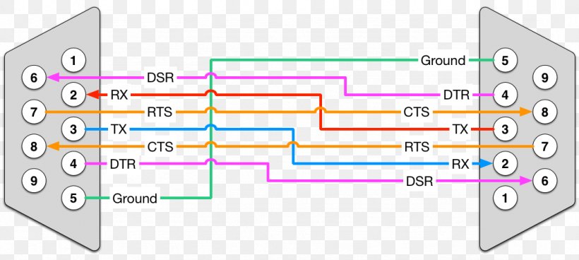
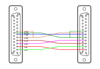
This cable may be used to connect any rs 232 equipped device to computer connect two computers via com serial port and so on. The null modem cable with loop back handshaking can be used with more software but it has no functional enhancements over the simple cable.

Null Modem Wikipedia
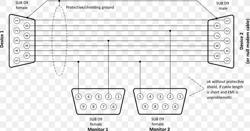
Null modem wiring diagram. Db9 connectors are designed to work with the eiatia 232 serial interface standard which determined the function of all nine pins as a standard. See also optec. Pinout of null modem cables and layout of 9 pin d sub female connector and 25 pin d sub female connectorde 9 to de 9 de 9 to de 25 cables. Rs232 null modem pinout and wiring. If the software is designed for using hardware flow control it seems to work with this null modem cable but on. But what is a null modem cable.
Null modem communication refers to using a crossed over rs 232 cable to connect the teleprinters directly to one. Here we have another image acheter câble série usb filaire croisé ftdi ft232r adaptateur usb. There is no way both devices can control data flow other than by using xonxoff handshaking. Null modem pinout to usb wiring diagram wiring library modem usb to db9 wiring diagram uploaded by yamama on tuesday february 12th 2019 in category usb wiring diagram. This is the simplest solution to connecting the two computers. The cable is comprised of three lines.
Db 9 connector pinout null modem wiring diagram. As we have seen null modem connections are made possible through the use of a null mode cable. The term db9 refers to a common connector type one of the d subminiature or d sub types of connectors. Use this cable to connect two devices equipped with serial rs 232 interface. Null modem is a communication method to directly connect two dtes computer terminal printer etc using an rs 232 serial cablethe name stems from the historical use of rs 232 cables to connect two teleprinter devices or two modems in order to communicate with one another. Serial and usb communications cables modem usb to db9 wiring diagram from usb wiring diagram topic.
The following schematic diagram show the male grey background and female black background pin numbering for db 9 connector. One wire serves as the signal ground with the other two lines.
