Pilot brake electronic brake controller time delayed wiring instructions for pilot trailer brake control part what can cause troubleshooting a reese pilot brake controller that says its connected all the time. Reese has always strived to provide the right trailer towing system for each application.

Reese Pilot Brake Controller
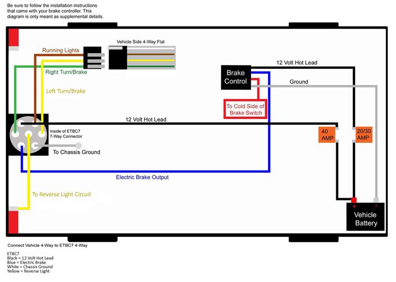
Reese pilot brake controller wiring diagram. Wire as shown at right. This is why we offer as many as ten different trailer hitches for a single vehicle. These units changed the company forever. Wiring instructions for pilot trailer brake control part 80550 replacement 7 way trailer connector for a 2000 dodge ram 3500 pilot brake controller only shows one red dot with trailer connected and no numbers with override. Secure all loose wires with cable ties so that they will not be damaged and reconnect battery. Brake controls that utilize the 2 plug style of wiring harness will be identified with the plug play logo.
See vehicles owners manual for special reconnection instructions. Reese has always strived to provide the right trailer towing system for each application. This is why we offer as many as ten different trailer hitches for a single vehicle. When the 70s came tekonsha engineering made a major break through they were the first to break new ground with an electronic brake control the sway control and the 2040. Whether your connecting a brake controller or wanting to run 15 30 or 50 amps of additional power hayman reeses plug and play smartclick wiring system makes it easier than ever to fit a range. This connection activates the trailer brakes once the brake pedal is applied.
In the mid 1960s they started manufacturing hydraulic brake controls 2014 2015. Reese trailer brake controller wiring diagram hayman reese trailer brake controller wiring diagram reese electric brake controller wiring diagram reese pilot trailer brake controller wiring diagram people today comprehend that trailer is a vehicle comprised of very complicated mechanisms. This vehicle is designed not just to travel one location to another but also to carry heavy loads. Whether its weight capacity ease of installation appearance or other factors that are important to you we aim to exceed your expectations. Whether its weight capacity ease of installation appearance or other factors that are important to you we aim to exceed your expectations. Locate the slide knob and power knob items a and b in the linked instructions diagram.
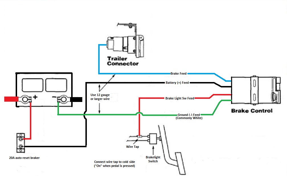
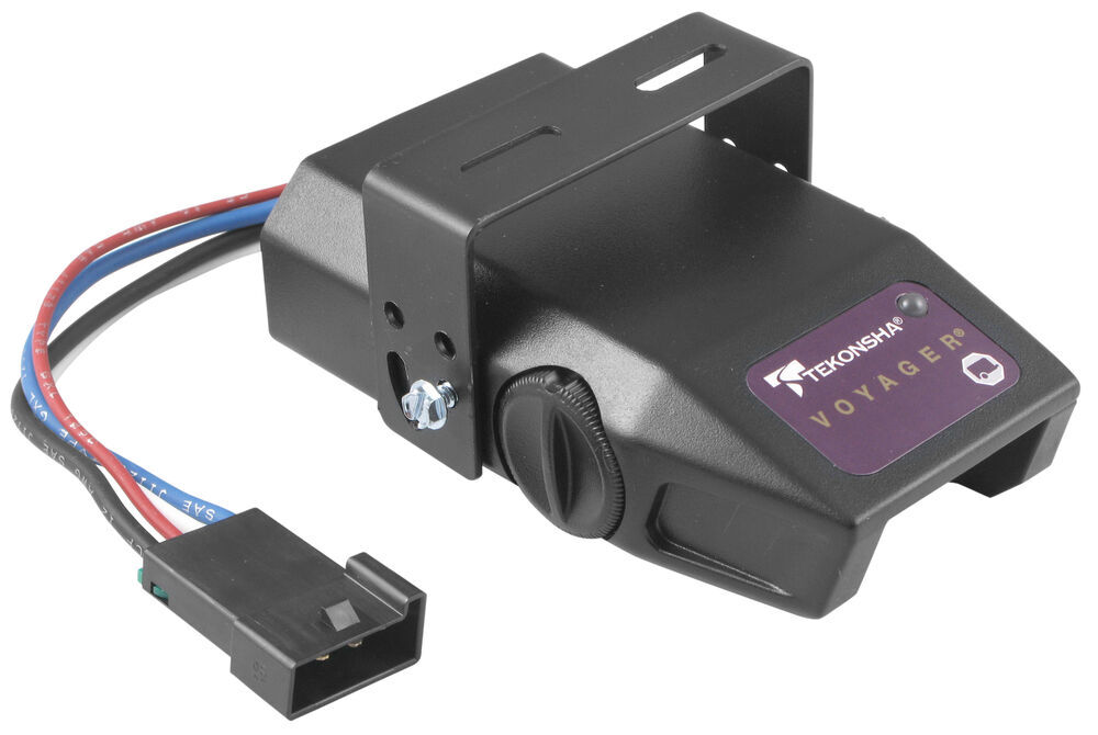
Bench test instructions 1. Simply plug the brake control end of the wiring harness into the back of the brake control and the vehicle end into the automobiles port. The blue wire carries the brake controller output voltage the white wire provides the ground connection and is usually ran to the negative battery terminal the black wire is the 12 volt power supply and the red wire typically connects to the brake stoplight switch located above the brake pedal. Using the wire tap provided splice the brake controls red stoplight wire to the light green wire.


