Since the hzm monitors the power at its screw terminals you can star or t tap the power connection. Fdcio422 for canadian branches author.

Basics Of Panelboards Siemens Cources Pdf Document
Siemens hcp wiring diagram. 4 wire transducer to 4 wire module i am a bit confused about m m and mana. Wiring should be connected to the nac circuits on the main board or the auxiliary power supply on the pad 4. Fhp product management fire safety subject. For the most up to date information refer to each products installation. Page 6 electrical ratings i t i l i f l l u siemens industry inc. Two 2 34 conduit knockouts one 1 12 conduit opening the inlet sampling tube length is determined by the width of the air duct being protected.
Cpu 1215c acdcrelay 6es7 215 1bg40 0xb0. The inlet tube f greater than and nearest to the duct width f should be used see. Additionally various siemens fire safety facps which include siemens modular as well as the 50 point 252 point and 504 point addressable facps can recognize model hcp devices. This marketing data sheet is not intended to be used for system design or installation purposes. 2 wire transducer to 2 wire module 2. 4 wire transducer to 2 wire module 4.
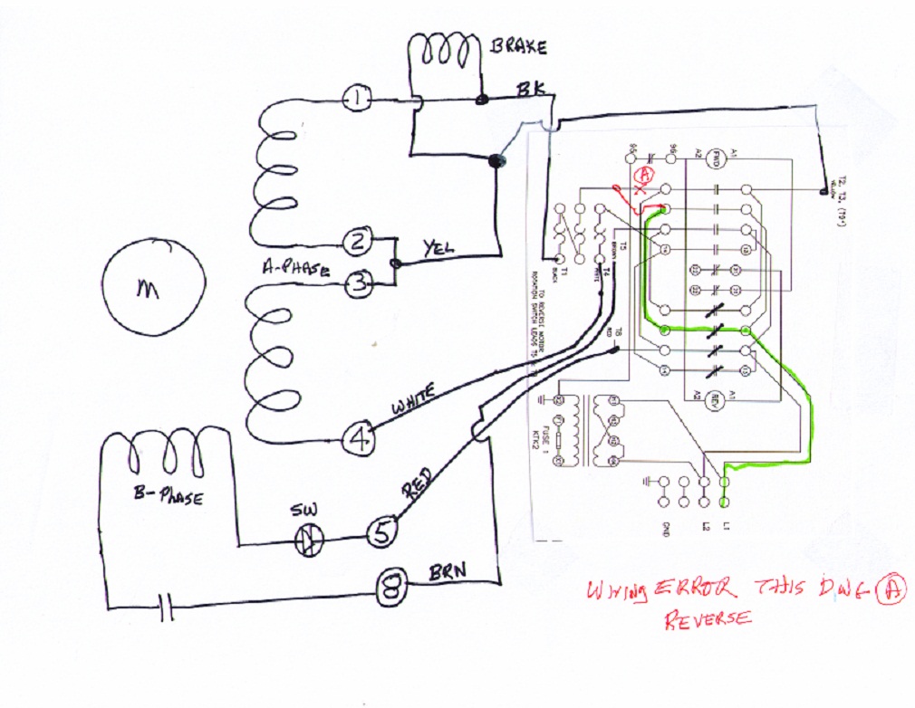
Pn 315 034850 8 building technologies division. Siemens motor control center wiring diagrams are at your fingertips within seconds. 3333 old milton parkway alpharetta ga 30005 siemens nema control 87 cut sheet1. Refer to figure 7 for the wiring diagram. 3 mounting diagram notice. Low voltage switchgear and other power distribution equipment.
Wwwsiemensca fire safety 1577 north service road l6h 0h6 canada tel. Wiring should be connected to tb3 on the psc 12 and psx 12 or the auxiliary power supply on the pad 4. The inlet tube can then be. Model hcp z can be configured as an independent remotely located telephone zone speaker zone or. Page 3 nec 760. Wiring diagrams for typical tiastar units tool.
Wiring diagrams size 1 4. 2 wire transducer to 4 wire module 3. Industry support siemens. Sampling tube selection table. I m new to control field. Siemens fires nac series of alarm signaling devices.
Use the tool below to quickly find and download one line diagrams. Page 3 5 siemens industry inc. I need wiring diagram to connect 2 wire and 4 wire transducer to analog input module for the following cases. For fs 250 systems the hcp is powered by the nac circuits and pad 4. Cpu 1215c wiring diagrams. The 24 vdc power may be wired only as class b.
Housing comes with three 3 wiring entry ports. Model fdcio422 is designed to provide the means for interfacing direct shorting devices to the device loop card model dlc. April 2014 supersedes sheet dated 1113 rev. Firefinder xls as well as the models fc2025 and fc2025 fire alarm control panels facps.

