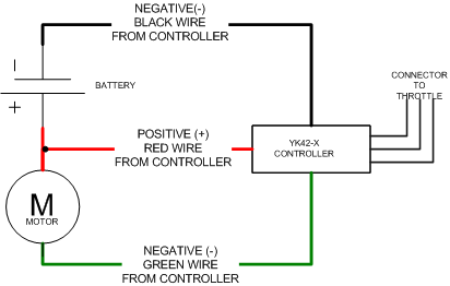
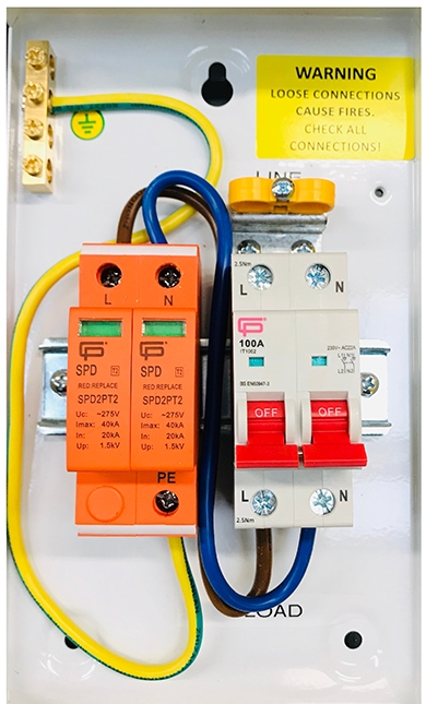
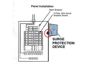
You must refer to this diagram while wiring the spd. You must refer to this diagram while wiring the spd.
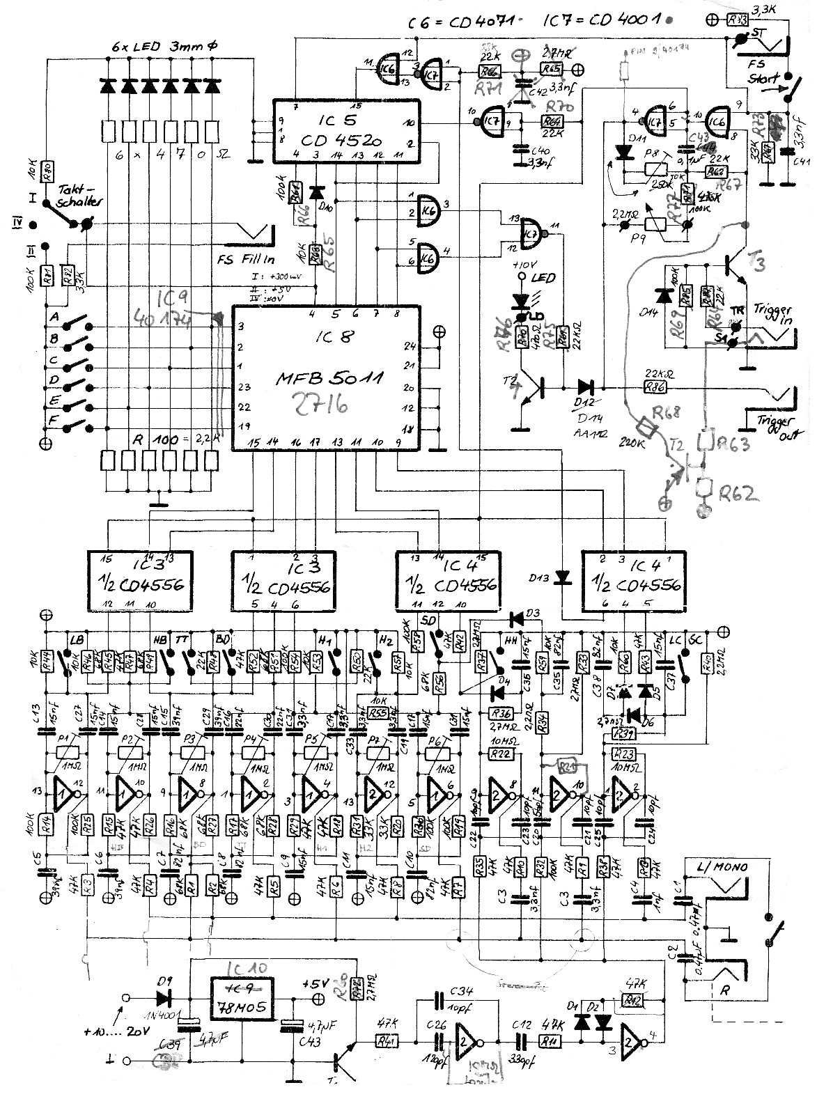
Ad11af Roland Spd Sx Owner Manual Wiring Library
Spd wiring diagram. The conductors used to connect the spd to the line or bus shall not be any longer than necessary and shall avoid unnecessary bends green wire the following represents a wiring diagram of spds in a typical system. Select the correct wiring diagram for the spd you are install ing. Spd wiring configuration 1. See figures 9 14. Spd wiring configuration 1. Wiring diagram book a1 15 b1 b2 16 18 b3 a2 b1 b3 15 supply voltage 16 18 l m h 2 levels b2 l1 f u 1 460 v f u 2 l2 l3 gnd h1 h3 h2 h4 f u 3 x1a f u 4 f u 5 x2a r.
Spd wiring configuration 2. Spd can be used with any electric panel that is within the spd ratings. Spd wires through the enclosure hole and mount the spd enclosure. Page 6 eaton spd series instruction manual im01005019e rev. Through the enclosure hole and mount the spd enclosure. Determine the wire length required to make the spd phase connections and cut the wires to the appropriate length.
You must refer to this diagram while wiring the spd. Wiring single phase units 230 l figure 8. Input and output conductors physically well separated and connected on the same terminal. Installation shown with midnite solar e combiner box. 5 surge protective device for integrated units effective november 2013 figure 6. Pv plus bus red wire battery negative black wire ground ac in blackred wire ac out blackred wire.
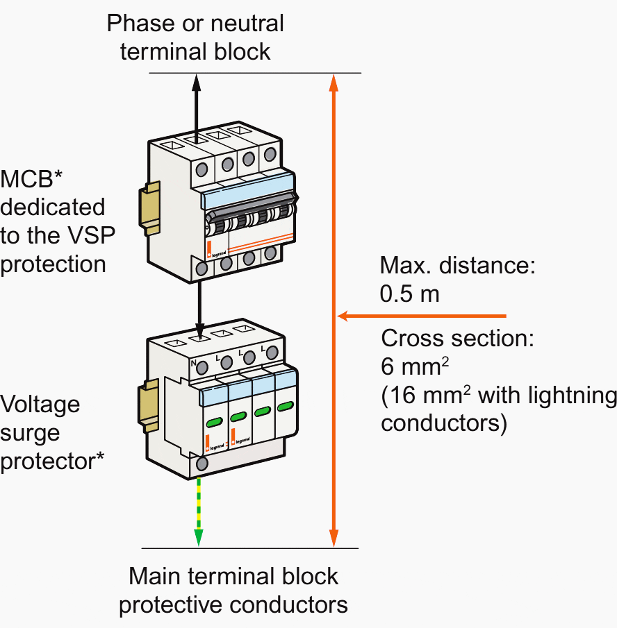
Upstream and downstream conductors connected on the voltage surge protector terminal with a common path. Select the correct wiring diagram for the spd you are install ing. Spd series type 1 and type 2 units do not require over current protection devices fuses or circuit break ers to operate correctly. Select the correct wiring diagram for the spd you are install ing. Fpv plus bus red wire battery negative black wire ground green wire ac in blackred ac out blackred wire. Wiring 3 phase delta units figure 7.
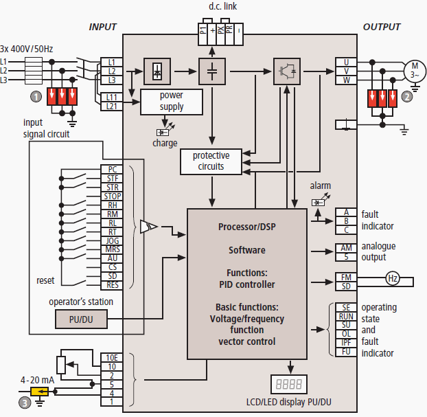
The following represents a wiring diagram of spds in a typical system. See figures 8 9 10 and 11 on page 7.


