Several transmitter wiring options exist. 4 20 ma transmitter wiring.
Wiring Diagram
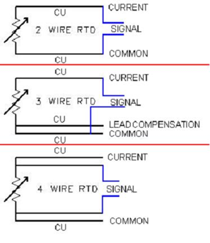
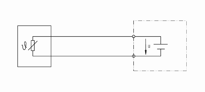
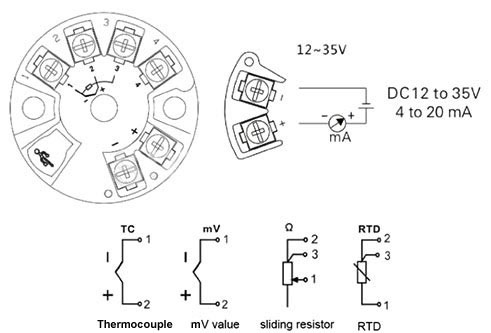
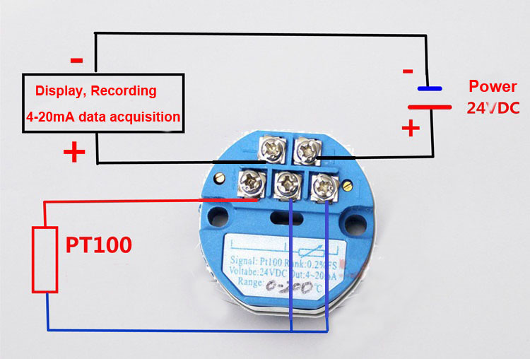
Temperature transmitter wiring diagram. Temperature sensor with single wire digital interface schematic circuit diagram. The best configuration for a specific application depends on a number of factors however the sensor configuration must match with transmitter otherwise leadwire resistance cancellation circuitry. The 2 wire 3 wire and 4 wire types are often used to describe the method of connection of electronic transmitters. Wiring diagrams x1351153001 r1 15 kω zone timed timed override rt1 thermistor temperature override on sw1 ω 10 k at 25c cancel sw2 signal common dwg source. There are 2 wiring methods for the rtd module and pt100 temperature sensors two wire and three wire connections. Wiring diagram pictures detail.
The rosemount 644 is a versatile temperature transmitter that delivers field reliability and advanced accuracy and stability to meet demanding process needs. When wiring with two wires first jumper across a1 and b1and a2 and b2 respectively then connect pt100 sensors and to the rtd module according to the following diagram on the left. These connection methods are of great concern to the instrument engineertechnician. Todays electronic process transmitters pressure temperature flow and level are connected in different wire types or configurations. The design of the associated control panel dictates which option should be used. 3270 3438 temperature sensors with fan control x1379084501 r9 15 kw r11 zero w zone timed timed.
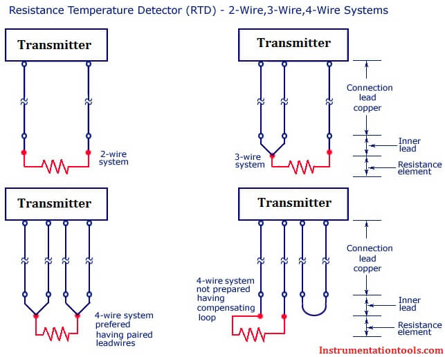
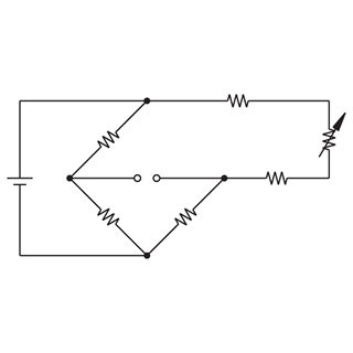
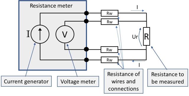
3 wire rtd connections the 3 wire rtd configuration is the most commonly used rtd circuit design and can be seen in industrial process and monitoring applications. A 2 wire rtd configuration is the most useful with high resistance sensors or in applications where a great deal of accuracy is not required. These wiring options include. A temperature measurement system with up to eight distributed temperature sensors can be realized using only a single signaling lead. Rtd pt100 3 wire wiring diagram amazon crocsee rtd pt100 temperature sensor probe 3 wires 2m cable thermocouple 58 572f 50 300c 1 2 npt thread industrial scientific. Current source transmitter non isolated 3 wire current sink transmitter non isolated 3 wire fully isolated 4 wire two wire loop powered transmitters.
A1b1 a2b2 and c1c2. Hart configuration with selectable hart revision capability revisions 5 or 7 accepts either one or two inputs from a wide variety of sensor types 2 3 and 4 wire rtd thermocouple mv and ohm. Difference between 2 wire rtd 3 wire rtd and 4 wire rtds rtds resistance temperature detectors are offered with 2 3 or 4 lead configuration. Easy wiring practices with captive sensor screw terminals an optimized wiring diagram and field mount enclosure option. The rosemount 644 head mount and field mount temperature transmitters support the following features.
Gallery of Temperature Transmitter Wiring Diagram