Once you have 24 volts move to step two. How this defrost control board works heat pump wiring for defrost cycle.
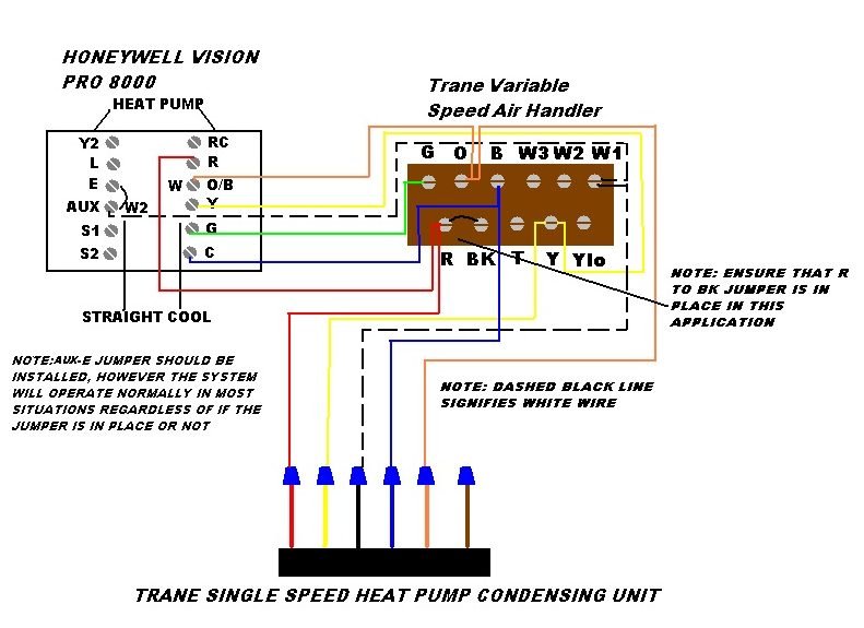
Wiring A Thermostat Furnace And Heat Pump For Dual Fuel Hybrid Heat
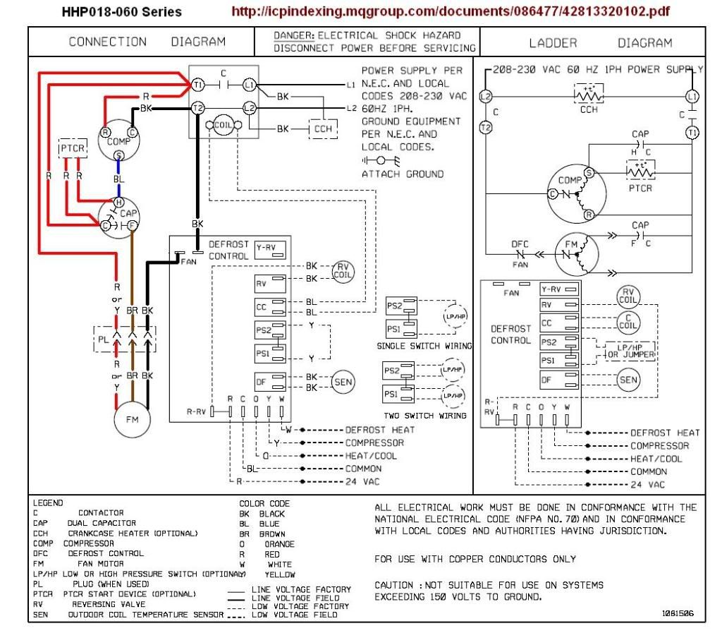
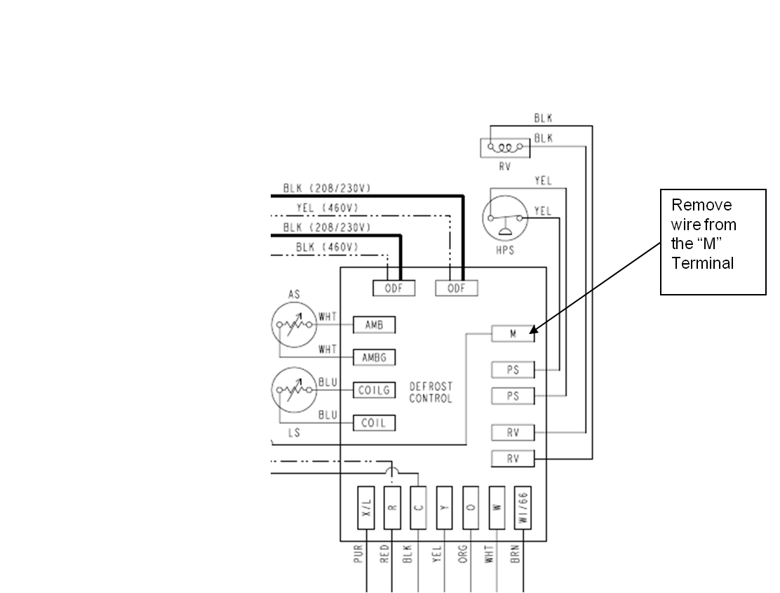
York defrost board wiring diagram. Replacement demand defrost control board. How to know if your heat pump defrost board is working properly so that it wont freeze up. Download 818 york heat pump pdf manuals. Connect one side of the 24 volt wiring from transformer to the wire going out to one side of the 24v contactor. Page 5 51516 n3y caution. W2 out output to energize 2nd stage heat when in defrost w166 used to energize 1st stage heat when in defrost.
York hvac wiring diagrams simple electronic circuits. Just a precautionary note this takes a lot of ram to run at least 32 meg. If it is then move to step two. Check to verify that the transformer is supplying 24 volts. Supervision is needed by a licensed hvac tech before doing this as experience and apprenticeship garners. S1 33101975102 computer hardware pdf manual download.
Furnace control board wiring diagram elegant goodman heat pump. Wiring diagram split system heat pump new goodman gas pack wiring. Goodman heat pump defrost board troubleshooting. Xl can be eliminated as the fault codes can be retrived from the board. To view the wiring diagrams download and install the free version of voloview express from autodesk. View and download york s1 33101975102 installation instructions online.
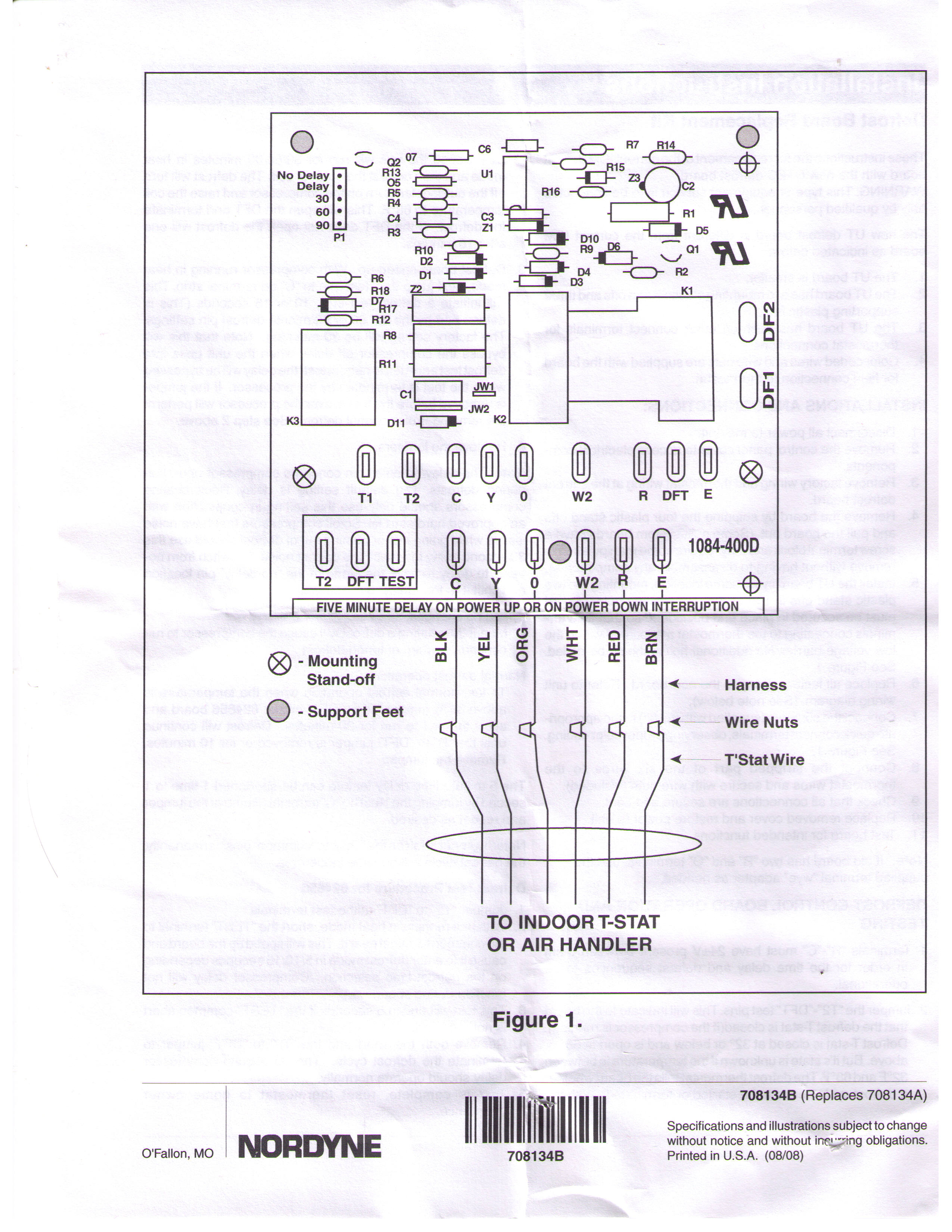
York retail system specific wiring diagrams january 2012. How to troubleshoot a defrost board. User manuals york heat pump operating guides and service manuals. W1 out output to energize 1st stage heat when in defrost. Electronic timer and defrost cycle start only when contactor is energized and defrost thermostat dft is closed below 36 f 22 c. If you do not replace transformer you may need to wire the transformer directly to the line power depending on how the board fried.
Goodman defrost board wiring diagram collections of goodman defrost board wiring diagram for 133 wire center. In the event that the retaining ring is missing do not 1. The valve body and possibly cause personal injury. Defrost the defrost board db is a time and tempera ture control which includes a field selectable time period between checks for frost 30 50 and 90 minutes. After installing autodesk view you can automatically open drawings from the web site by simply clicking on. If the valve stem is backed out beyond the retaining the wiring diagram inside the unit control box cover before ring system pressure could force the stem out of connecting to power supply.
Gallery of York Defrost Board Wiring Diagram


__11597.1574800675.jpg?c=1)