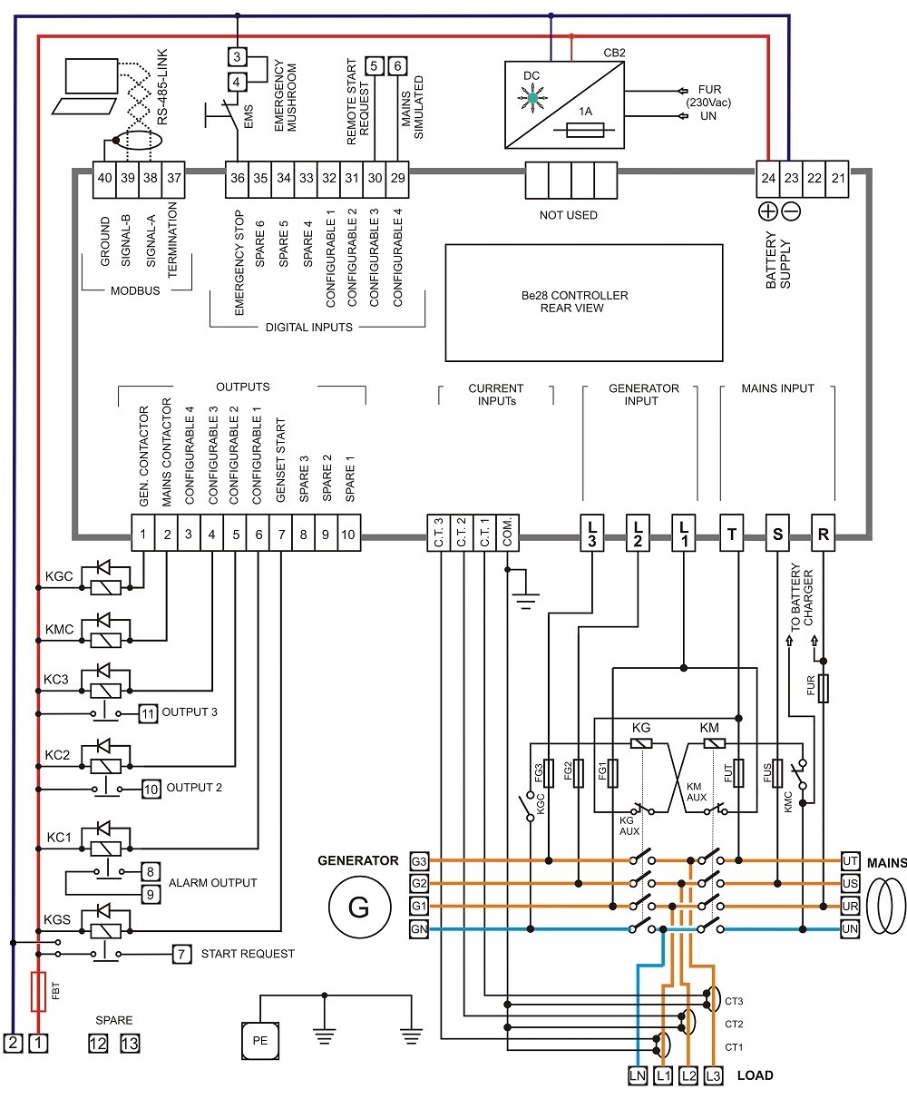
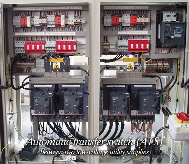
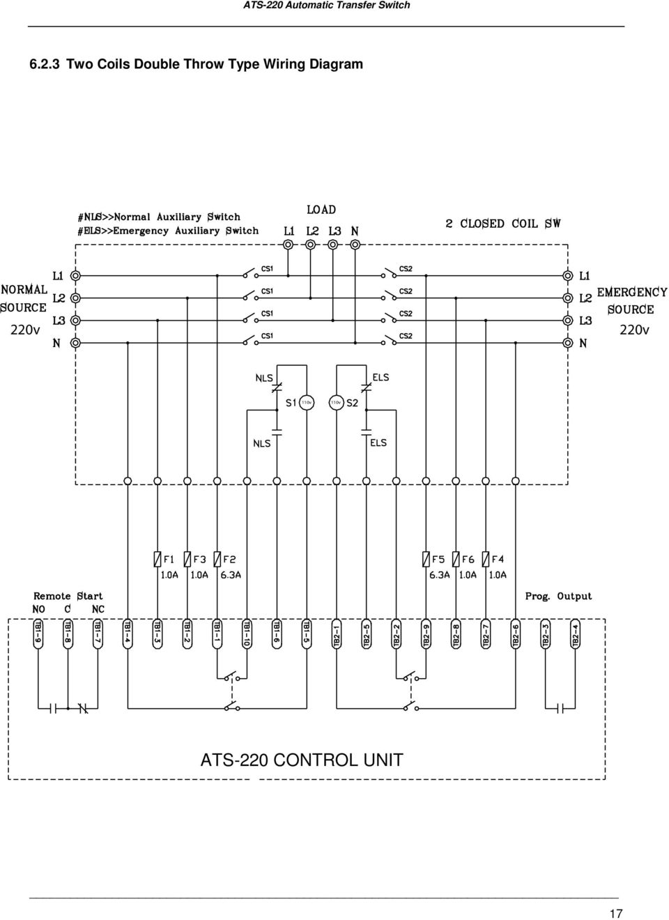
Ats wiring diagram free download as pdf file pdf or read online for free. Does anyone have a proper wiring schematic that would aid me in wiring my rv surge electrical protector to a parallax ats.
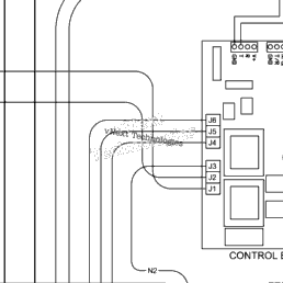
Briggs Amp Stratton Power Products 040450 01 10 000 Watt
Ats wiring diagram. Cutler hammer automatic transfer switch wiring diagrams directions for use the drawing package can be used a s a point to point wiring diagram for maintenance and diagnostic purposes for solid state logic spb transfer switches all voltages. To avoid possible injury that might be caused by such sudden start ups the systems automatic start circuit must be disabled before working on or around the generator or transfer switch. A wiring diagram is a simplified conventional photographic depiction of an electric circuit. A wiring diagram is a straightforward graph of the physical links as well as physical design of an electric system or circuit. September 11 2018 by larry a. When an automatic transfer switch is installed for a standby generator set the generator engine may crank and start at any time without warning.
Wellborn variety of ats wiring diagram for standby generator. It shows the elements of the circuit as streamlined shapes as well as the power and also signal links between the gadgets. Auto transfer switch wiring diagram connection diagram. It reveals how the electrical wires are interconnected as well as can additionally show where fixtures as well as components may be linked to the system. Asco 7000 series product wiring diagrams. When and also ways to utilize a wiring diagram.
I called parallax about the wiring for the ats and what he had to look at the link nash gave it is a pdf of the wiring diagram neededthis power transfer switch has the same great features as the 30 amp ats and more. All the wiring connections are same as above for manual operation of three phase changeover switch but the switching operation is automatic. Standard diagrams transfer between 2 sources 3 bus bars comut 050 a t1 t2 q2 q4 ats q1 q3 ats cl cl ncl q5 comut 049 a t1 cl cl p1 p3 ncl p2 t2 p4 standard solution socomec solution 1 sources are 2 transformers 2 sources are 1 transformer and 1 genset comut 052 a t1 q3 q1 q2 ats ncl clcl g comut 051 a t1 p1 p3 p4 ncl p2 standard socomec. Fig 5 shows 4 poles 3 phase automatic transfer switch ats connection to the main distribution board.

