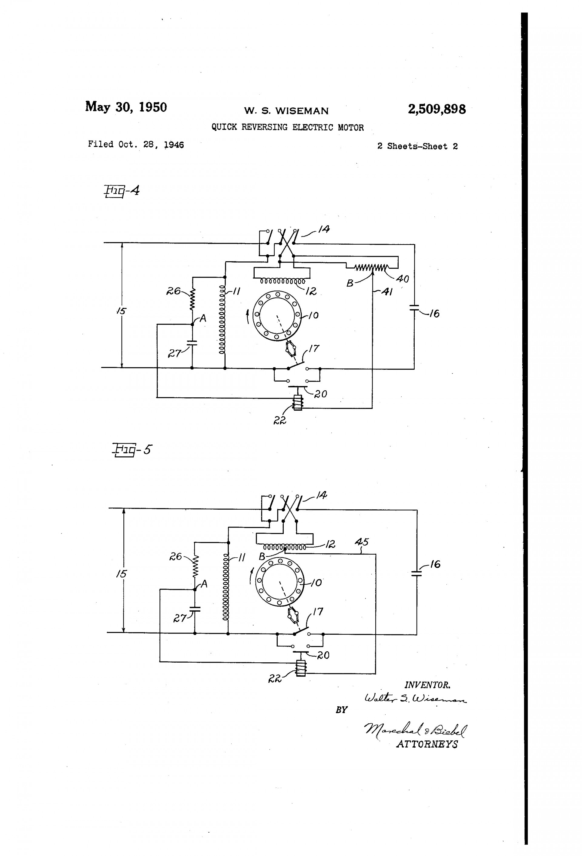
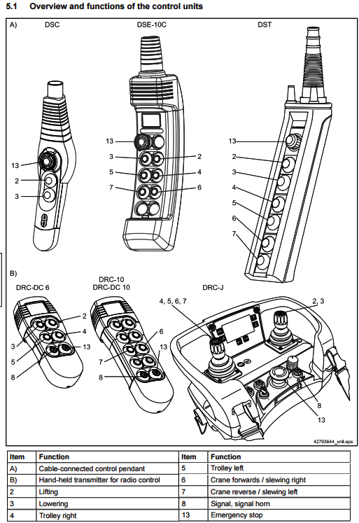
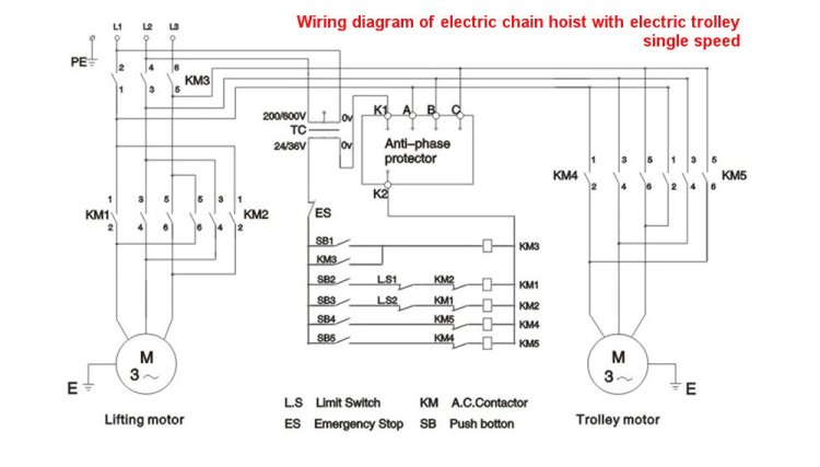
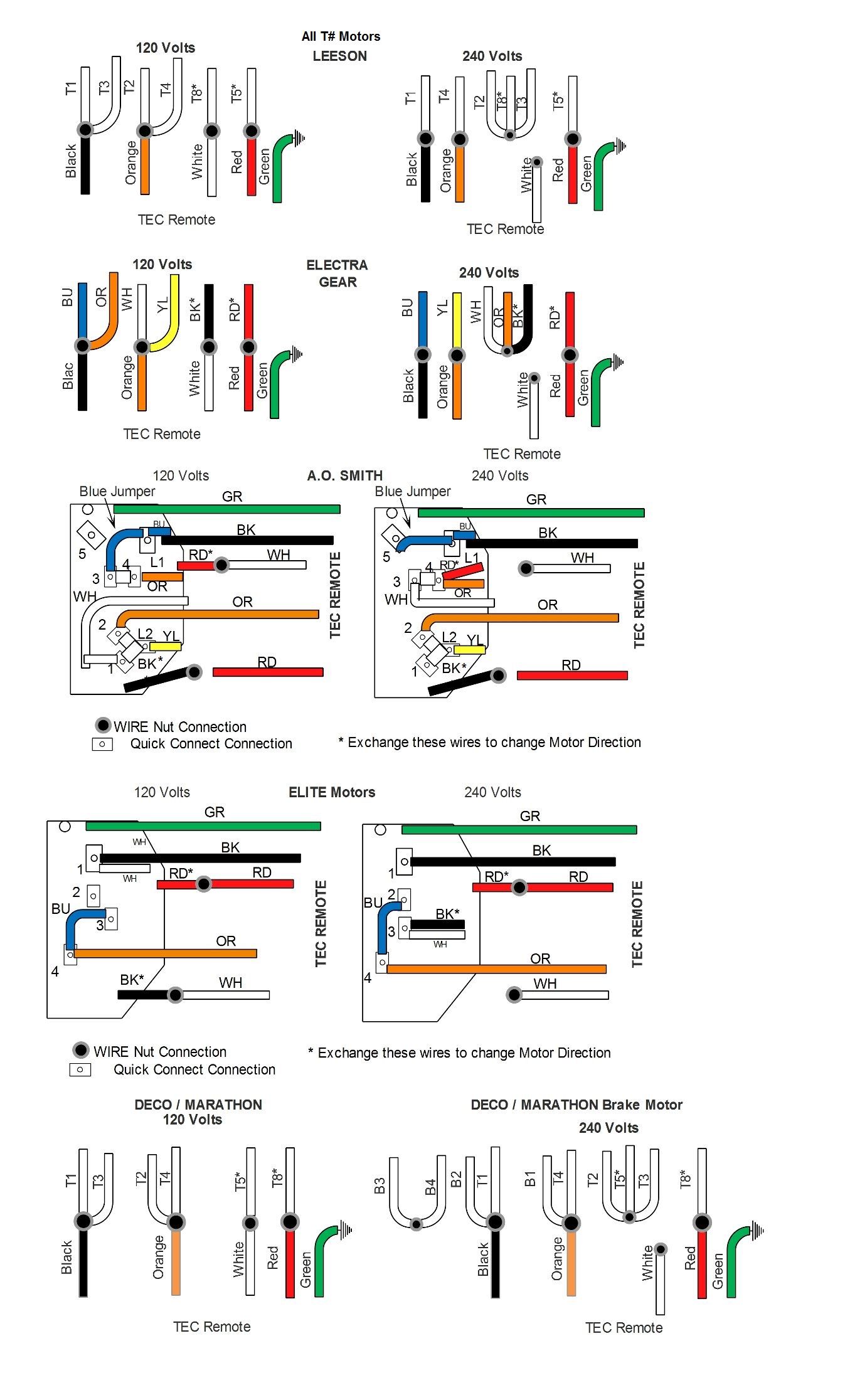
For rapid brake reaction time incorporate the contact as shown on the brake diagram lo cated on the inside of the motor conduit box lid. Demag chain hoist wiring diagram wiring diagram and schematic intended for demag hoist wiring diagram image size x px and to view image details please click the image.

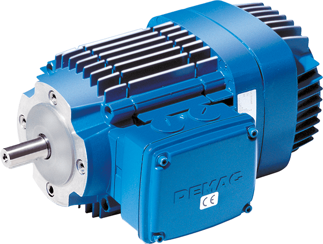
Demag Zba132b4 Cylindrical Rotor Motor Crane Hoist With Wgb70td Gearbox
Demag motor wiring diagram. 230 460 volts 60 hz brake motor connection. Here is a picture gallery about demag hoist wiring diagram complete with the description of the image please find the image you need. Nections shown on this page are for normal brake reaction time. Brake motor connection single speed dual voltage connection diagram dt72 example motor voltages. Our conical rotor brake motors with outputs of up to 88 hp 55 kw are a proven solution for stopping and starting drives and direct line fed travel applications. Demag dc chain hoist and important information if you ever have to contact the manufacturer or his representative.
One contactor burnt for high speed and a replced contactor does not engange originally the coils re fed with a nutural and the one i replaced is only working with a phase. Motor brake couplings shaft or gear ing. Inst maint wiringqxd 5032008 1002 am page 6. Owner where in use size serial number year of manufacture operating voltage control voltage frequency wiring diagram number tab. Hoist motor demag kbh conical rotor brake motor over 3 million motors in industrial use. 1 example of a rating plate item designation 1 manufacturer see above 2 chain hoist type.
A sbestos free non polluting brake linings. Our type z cylindrical rotor brake motors drive efficiency and availability and are engineered to perfectly match our gearbox range. Many single speed two speed and micro speed motor types for each dh wire rope hoist. These diagrams are current at the time of publication check the wiring diagram supplied with the motor. Available as an option is the load hold holding brake. If you are working on two speed motor wiring you will need an ac power supply the two speed motor and a double pole double throw switch.
By connecting the proper wires to the high and low speed terminals on the motor and switch you can control how fast or slow it turns once powered up. Our drive motors perform a wide variety of industrial drive tasks reliably and effectively. Simple robust and reliable these are the key characteristics of our kb conical rotor brake motors. Combination of gearboxes and motors using demag coupling shaft end z type cylindrical rotor motors or kb type conical rotor brake motors via an intermediate flange and roller spider coupling. This is due to the mechanical connection between the brake and rotor. Kindly email me the diagrams for star deltor and direct online for a 3speed 1directon 3ph motor have two of them in a bow cutter.
Since there is no oil present in the coupling housing gearboxes can be fitted independent of the motor and the motors can be easily disassembled. Their unique brake operating principle eliminates the need for separate control or additional switching elements. Please help how to go about this. Refer to the motor manufacturers data on the motor for wiring diagrams on standard frame ex e ex d etc.
