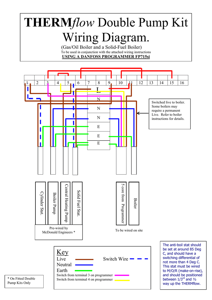
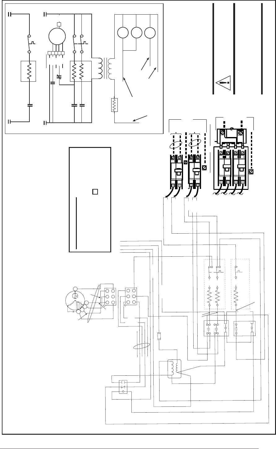
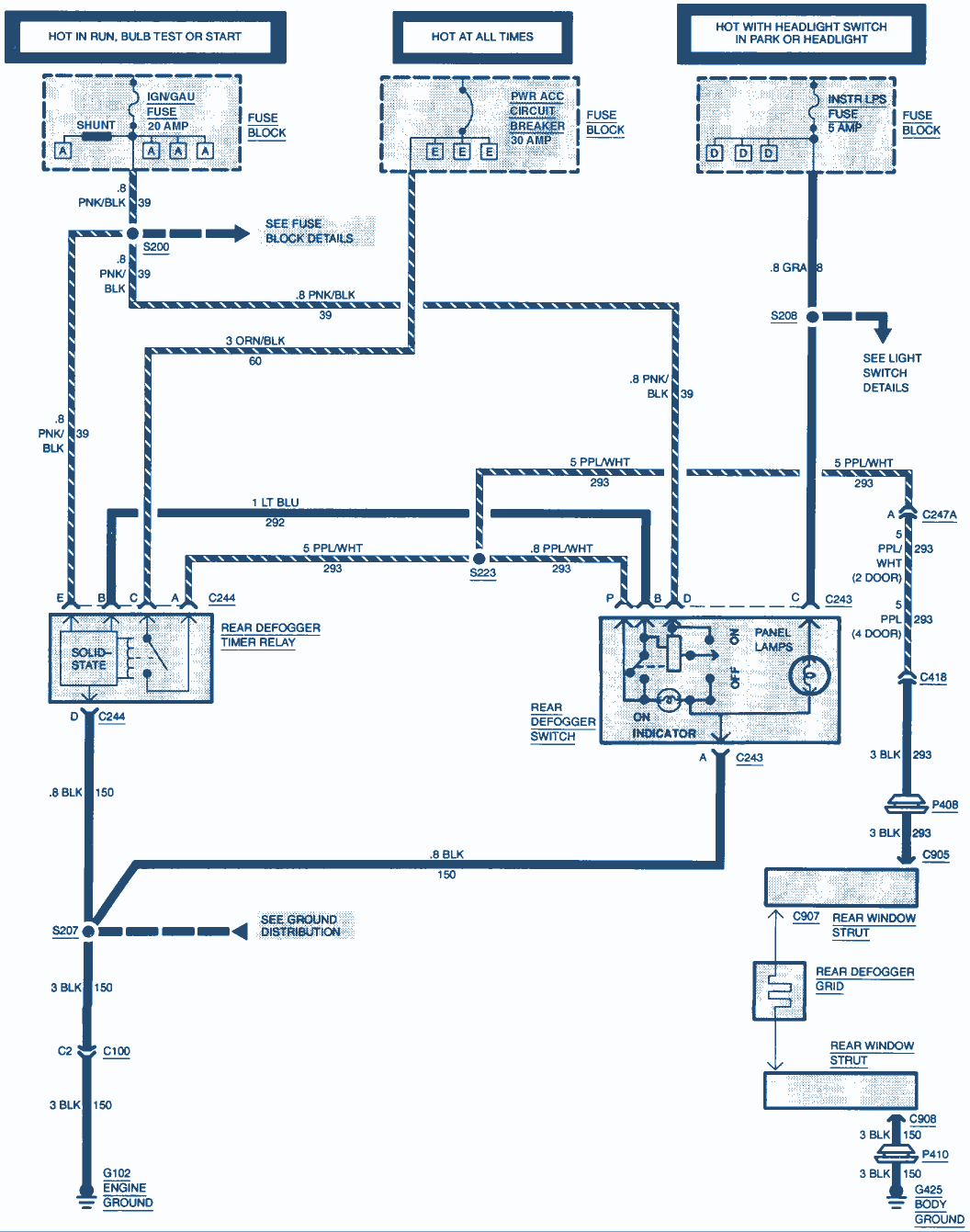
Assortment of pump control panel wiring diagram schematic. A wiring diagram is a simplified standard photographic depiction of an electrical circuit.

Gas Station Pump Wiring Diagram
Gas pump wiring diagram. Series 9800k pumps and dispensers installationoperation manual. It shows the parts of the circuit as simplified shapes as well as the power as well as signal links between the devices. Fuel pump ground circuit fuel level sensor signal circuit fuel pump power circuit fuel pump ground circuit fuel level sensor signal circuit fuel pump power circuit fuel level sensor reference low circuit wire 1. Wire color is black wire 2. Variety of electric fuel pump relay wiring diagram. Associated pool wiring underground wiring.
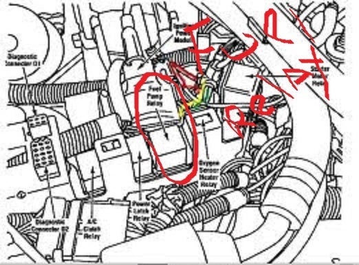
This typical circuit diagram of the fuel pump circuit applies to the gasoline 1993 1994 and 1995 ford f150 f250 and f350 equipped with a gasoline 49l or a 50l or a 58l engine and dual fuel tanks. Fe 357 atlas pump retailcommercial field wiring diagram. More 49l 50l and 58l ford tutorials. If conduit for the diesel dispenser passes through the class i division 1 or 2 areas around the gasoline dispenser the wiring methods and sealing requirements in article 501 apply see figure 2 ec514 02 514 03a. Wire color is grey wire 4. But it is common to wire diesel fuel dispensers adjacent to gasoline dispensers.
Fe 356 atlas dispenser retailcommercial field wiring diagram. Wire color may be purple orange or black wire 5. Wire color is purple wire 3. Atlas wiring diagrams. It shows the elements of the circuit as streamlined shapes and the power as well as signal links in between the gadgets. You can find the 1996 f series pick up fuel pump circuit diagram here.
Fuel pump wiring diagram 1996 f150 f250 f350. Fe 361 atlas master satellite field wiring diagram. Gas station lighting advice please. A wiring diagram is a simplified traditional photographic depiction of an electric circuit. Any one knows electrical sub station tendering.


