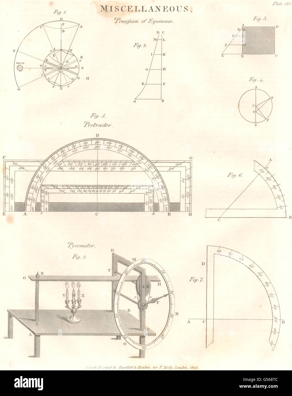
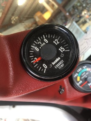
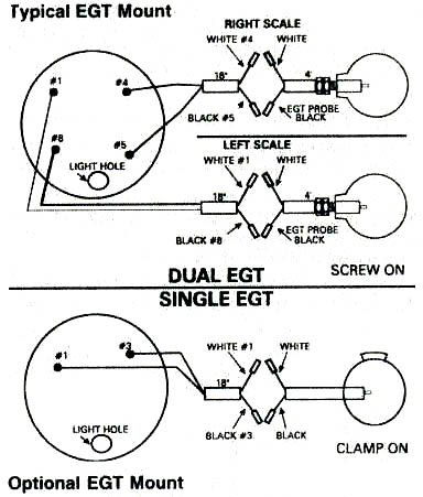
Isspro pyrometer wiring diagram isspro pyrometer wiring diagram in isspro pyrometer wiring diagram image size 366 x 366 px and to view image details please click the image. Color pyrometers are used to measure the radiation emitted from the object during the temperature measurement.

Caterpillar 3208 Wiring Diagram Marine Diagram Marine
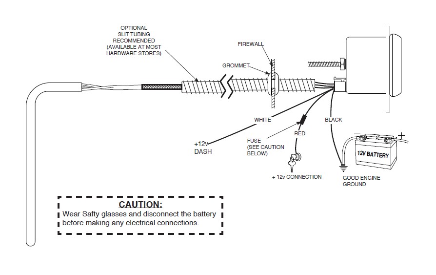
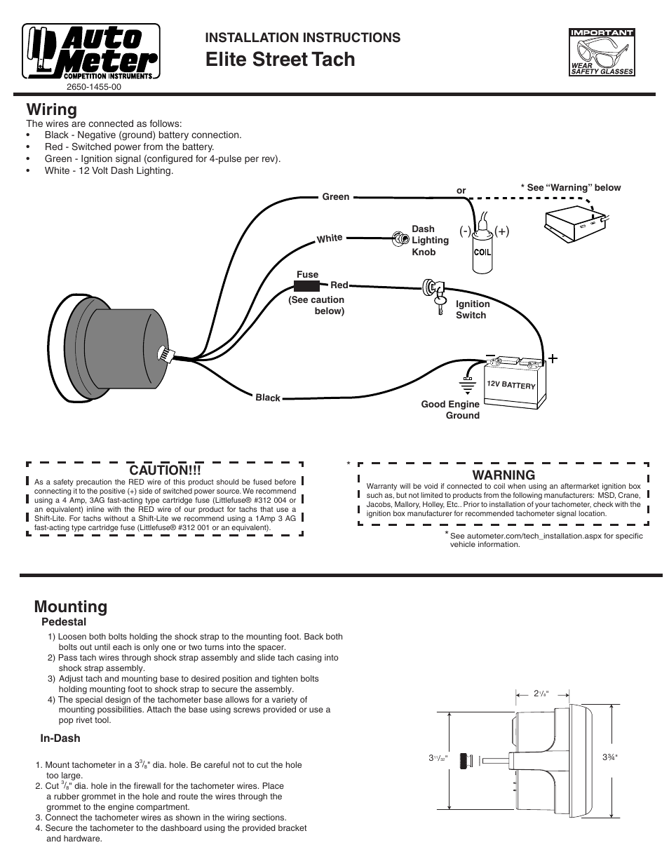
Pyrometer wiring diagram. Ab cb61 body batt. Pyrometer r602 requires a 2 ¾ mounting hole. These can measure the objects temperature very accurately. Wiring a relay for gauge controlled output. Do not deviate from assembly or wiring instructions. Autometer gauge wiring diagram youll need a comprehensive professional and easy to know wiring diagram.
Read these instructions thoroughly before making installation. Brkr cigar lighter 15a a b f71 fuse trans batt 10a a b f25 fuse hvac cab 30a a b x2d108 frc1b2 f63 fuse instr cluster ems 5a a b f64 fuse dpf ign b10a f69 fuse eat ems 5a b frc1b1 spx2d relay ems 1 85 rly01 86 30 87a 87. Pyrometer 2¹₁₆ 52 mm diameter 1 2. Remove dampening wires across the meter terminals. Lamp socket push in wedge type 1 3. Pyrometer 2 116 spek pro professional racing gauge optional.
A wiring diagram is a simplified conventional pictorial representation of an electric circuit. Brkr open a b cb68 cir. Dimmer connect the orange wire to the factory gauge dimmer circuit by either tapping into the in cab fuse block or by connecting directly to the wire running from the dimmer on the headlight. Power distribution 22 wiring diagram. Light bulb 12 volt ge. If the circuit does not have a fuse or the existing fuse is higher than 1 amp use an inline fuse.
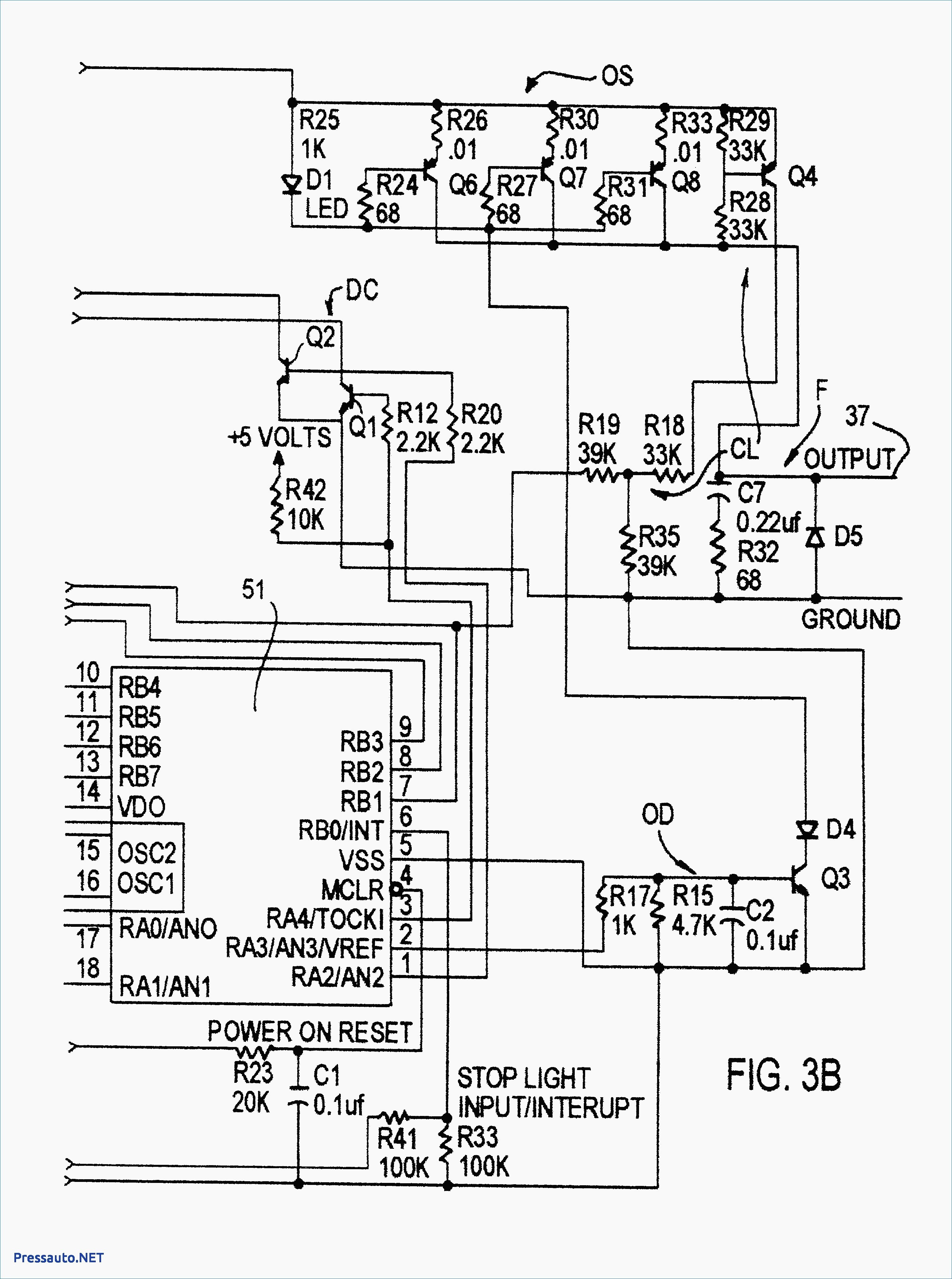
Pyrometers r604 r606 and r624 require a 3 mounting hole. Vdo mounting bracket and nuts 1 5. Here we installed a gm factory match transmission temp boost and egt pyrometer on a tow truck equipped with the chevygmc duramax. Hence the measuring errors are very low with these devices. It shows the elements of the circuit as simplified forms and the power and signal connections in between the devices. Stud 20a a b cb67 cir.
Autometer gps speedometer installation and usage. Begin by installing the thermocouple in the exhaust. 158 or equivalent 1 4. Pyrometers r605 and r607 require a 2 116 mounting hole. Variety of autometer gauge wiring diagram. For turbo engines install the probe 1 2 inches from the turbo exhaust outlet or you.
Mount the pyrometer through the instrument panel or use mounting bracket at the desired position. Installation instructions 1 caution. Here is a picture gallery about isspro pyrometer wiring diagram complete with the description of the image please find the image you need. Wire should be fused so as not to exceed 1 amp. With this kind of an illustrative guide you are going to have the ability to troubleshoot avoid and total your projects easily. Find product manuals and wiring diagrams for your auto meter product.
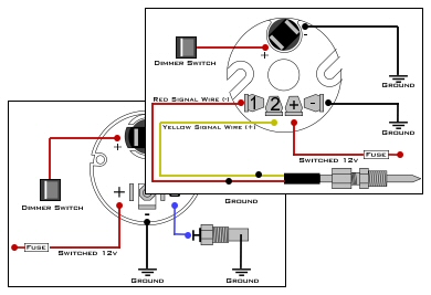
Diagram 1 diagram 2 wiring installation instructions for.


