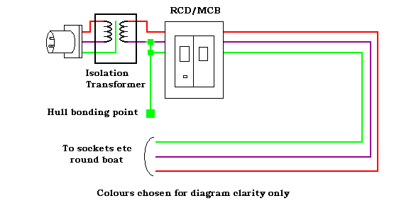
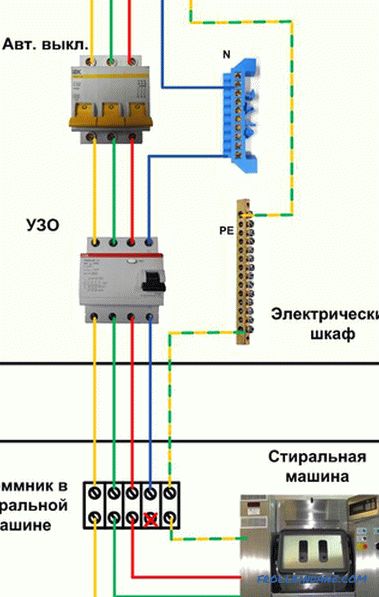
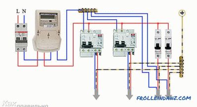
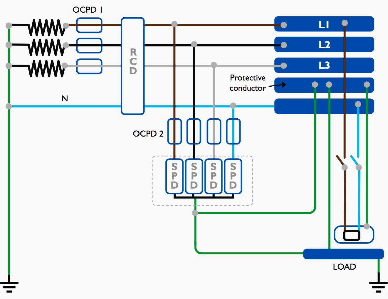
The detailed internal wiring for the sample db and mcbs and rcd units used. The same description and detailes can be used as mentioned for the above fig 1.

053a23 Volkswagen Rcd 310 Wiring Diagram Wiring Library
Rcd wiring diagram. Now get hot wire phase from the rcd breaker and connect to all one pole mcb breakers and neutral to neutral bus bar as i shown in the above rcd diagram. The three phase wiring for gfci or rcd rccb or rcbo wiring diagram shows the three lines l1 l2 and l3 and neutral has been connected as input to the rccb from main board followed by mcb ie. Socket outlet rcds these are special socket outlets with an rcd built into them which can be used in place of a standard socket outlet. The fixed rcd wiring diagram is very simple just link 2 pole circuit breaker in 2 pole fixed rcd circuit breaker we have to incoming connectionterminals where we connect the incoming or entering supply and 2 connection pointterminals for getting supply for better understanding follow the below diagram. A wiring diagram is a simple visual representation of the physical connections and physical layout of an electrical system or circuit. It shows how the electrical wires are interconnected and can also show where fixtures and components may be connected to the system.
For wiring of voltmeter and indicator you need to connect the phase supply from the breaker and neutral wire to neutral connection point. Demand of these three circuits must not exceed rating of rcd ol n n n a neutral link do not earth ol clipsal rcd 2 4n 1 3n a mains switch a e n n an. A fixed rcd provides the highest level of protection as it protects all the wiring and the sockets on a circuit and any connected appliances. First you need to get supply from the main double pole circuit breaker and connect to the rcd fixed rcd breaker as i shown in the above rcd wiring diagram. The lower four terminals and ground wire of rcbo has been connected to the spa control box by the following sequence. Wiring diagram of single phase distribution board with rcd in nec us iec uk eu electrical wiring color codes.
Dual rcd consumer unit wiring diagram wiring diagram is a simplified adequate pictorial representation of an electrical circuit. Clipsal rc and 4rc series residual current device wiring diagrams 1 2 main switch single phase e 3n 4n clipsal rcbm 4rcbm and 4rcbe series combined mcbrcd wiring diagram a warning combined max. Below is the given wiring diagram of single phase distribution board with rcd in both nec and iec electrical wiring color codes. It shows the components of the circuit as simplified shapes and the capacity and signal friends together with the devices.

