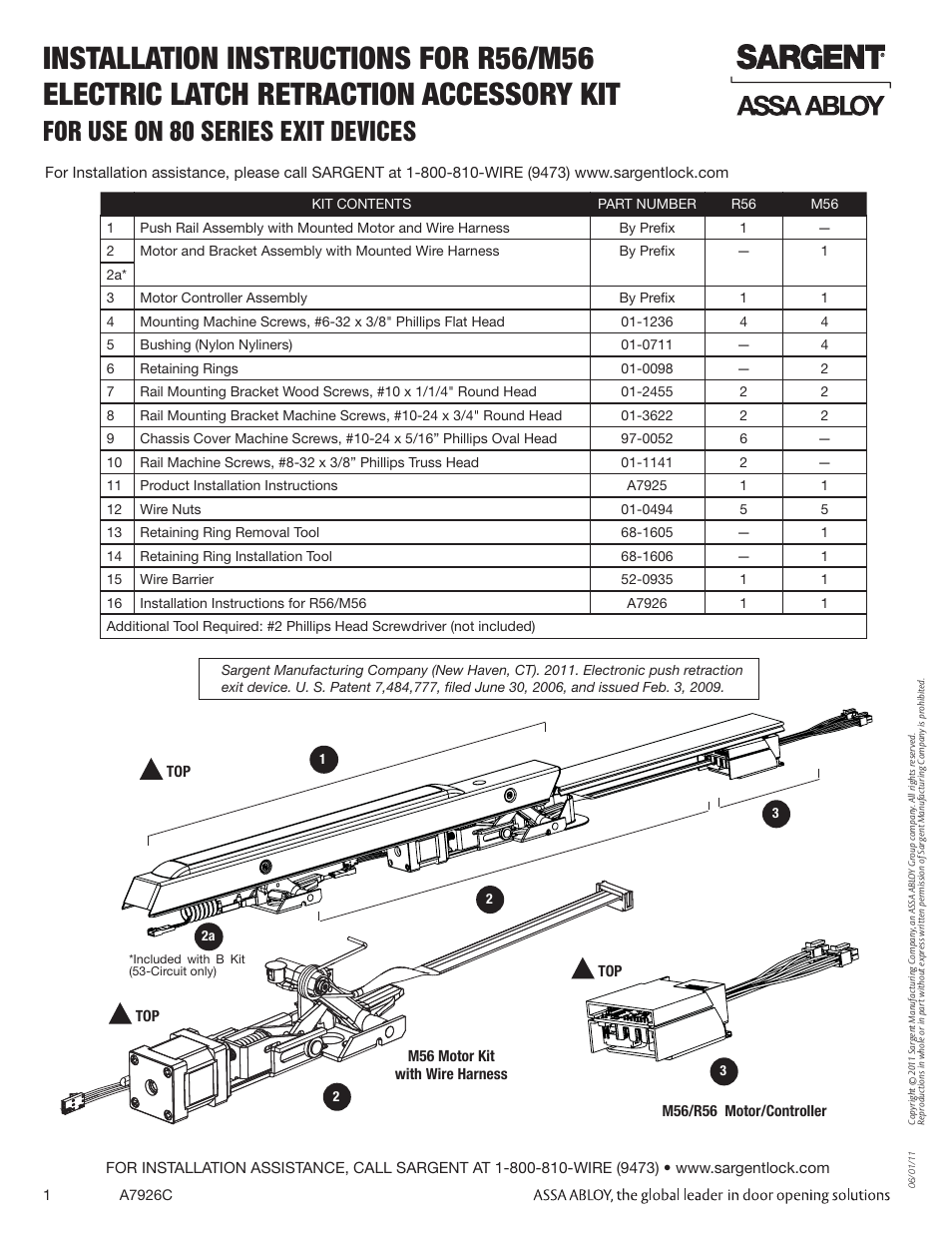
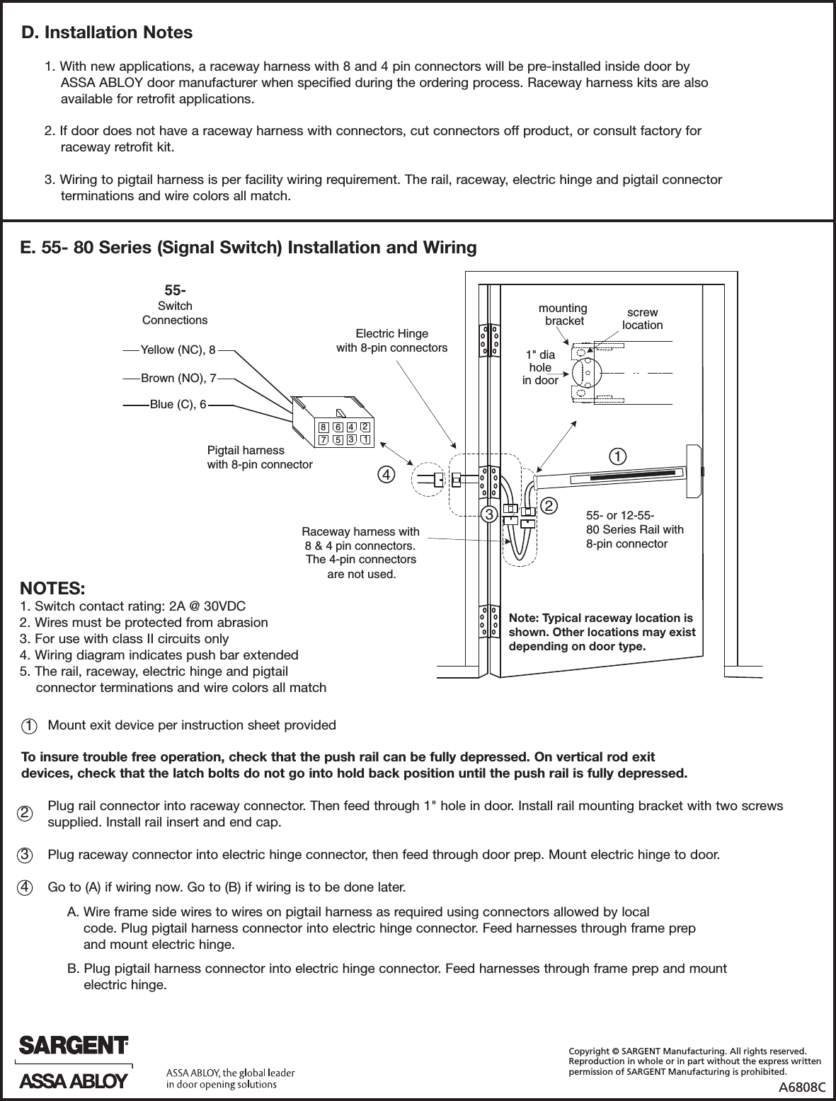
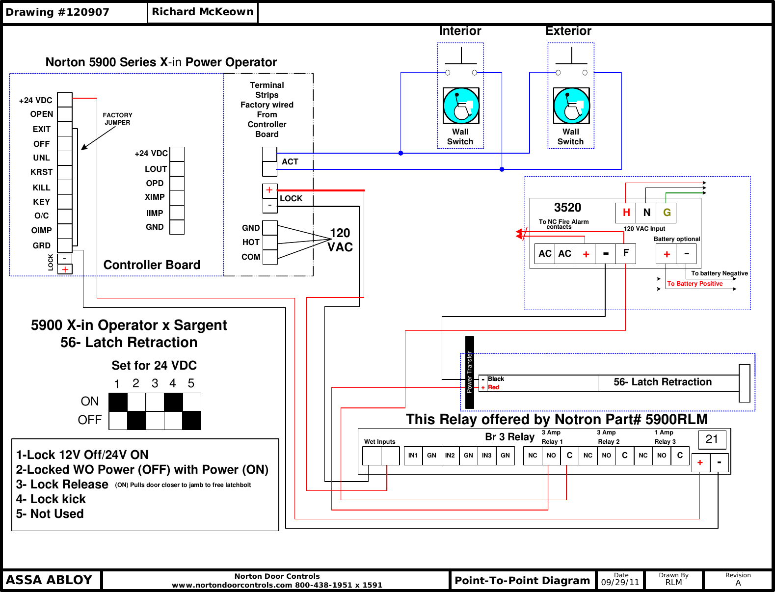
Instructions for installation and wiring remote options to sargent al prefix 80 series alarmed exit devices using the 546 wiring harness to electrolynx connector system. If a sargent product is modified it may no longer meet industry certification and quality control standards applicable to the original product and is no longer a genuine sargent product.

Sargent Catalog Cuts Door Antimicrobial Free 30 Day
Sargent 80 series wiring diagram. 12 53 nb md 8406 8410 8413 8415 8440. Installation instructions for 988988cr988y surface bolt. Function when the 58 80 series exit device is energized and the rail is depressed it will continuously hold the push rail. Installation and wiring instructions for tl 53 55 56 80 series exit device. Installation instructions for sargent 80 series exit devices. Ideal for environments that require strong and durable security solutions the 80 series exit devices exceed ansibhma grade 1 requirements for cycle and strength and support unique applications including delayed egress alarmed exit and electric latch retraction.
If you need assistance please call the sargent technical support team at 1 800 810 wire 1 800 810 9473. Information on wiring diagrams will be uploaded shortly.


