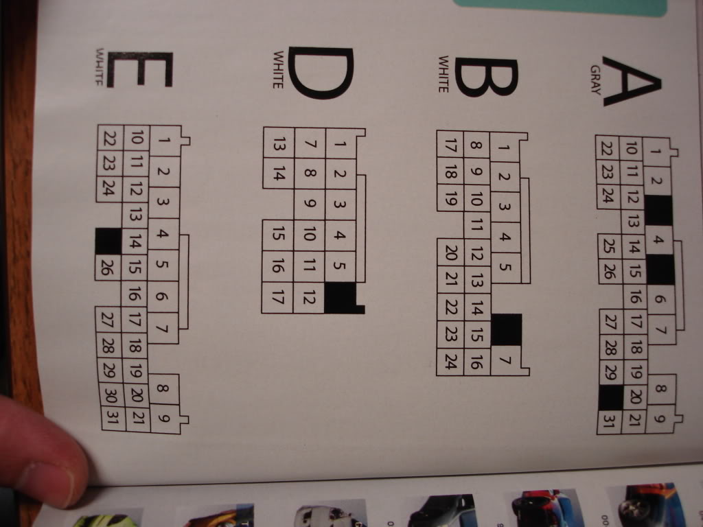
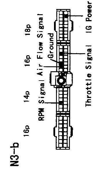
401 a917 is applicable and ecu terminal arrangement drawings. 2 contents chapter 1 introduction safety precautions 4 features of this product 6.

Rb25det Tps Wiring Diagram Rbdet Tps Wiring Diagram Rbdet
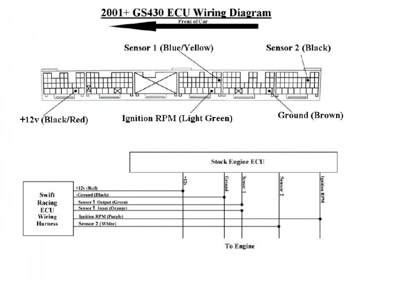
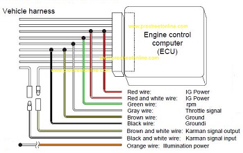
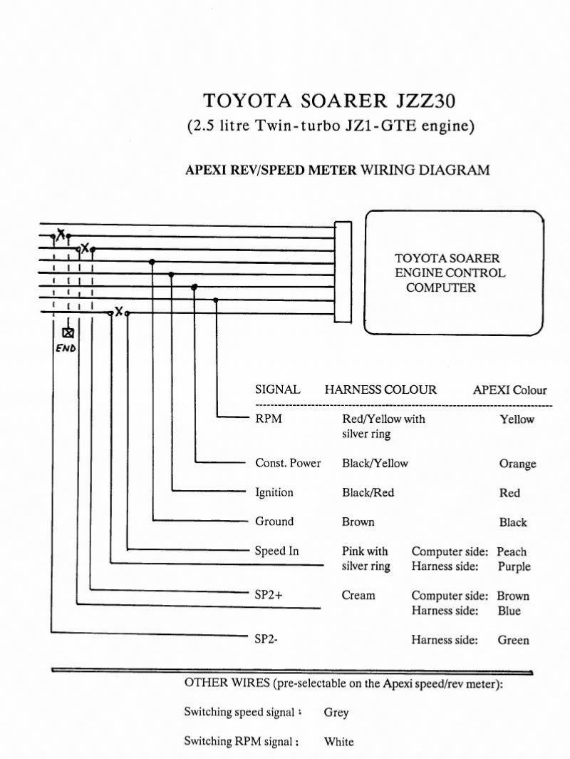
Apexi neo wiring diagram. Afc neo wiring diagram vafc2 wiring diagram wiring diagram afc neo wiring diagram wiring diagram is a simplified tolerable pictorial representation of an electrical circuit. Wiring diagrams and ecujan 01 hyundai tiburon apexi safc neo wiring diagram hyundai tiburon v6 ecm connector location. 3connect the harness attached to the super afc ii securely to the power cable of the vehicle harness grounding wire engine rpm signal wire throttle signal wire and knocking signal wire from to the ecu by referring to the vehicle specific wiring diagram. Wiring diagram by model this document describes car models to which the afc neo product code. It shows the components of the circuit as simplified shapes and the knack and signal links between the devices. The afc neo extension harness is ideal for use on vehicle applications where the ecuecm is located away from the drivers cockpit and dashboard.
When installing the afc neo both this document and the instruction manual are required. Referring to the vehicle specific wiring diagram. Exhaust system manuals center pipe 144 n052 downpipes 145 m005 gt spec 172 kt05 172 kh14 172 kh13. For the operating method and precautions for the afc neo refer to the instruction manual. Apexi product manuals find product manuals wiring diagrams other useful information for the apexi product catalog. How to view the ecu diagrams 7 installation diagram selection tak 8 connection diagram 12 10 connection diagram 34 11 connection diagram 56 12 toyota application chart 13 ecu diagram 20 nissan application chart 24 ecu diagram 28 honda application chart 30 ecu diagram 33.
The neo harness has 9 wires used for the manufacturer. Vehicle specific wiring diagram type select 20p nissan vehicle 300zx s line gt r skyline gt r sk line s line silvia silvia leosx code engine t e year 232 bcnr33 rb26dett ecu r32 s 14 s13 rb25dt sr20det ca 13det the no on the left side is to limit timing adjustments pos pos. Refer to page 8 and page 9. Car models mentioned in the wiring diagram by model airflowpressure sensor signal adjustment product name product code applicable car models application.


